Quick disconnect for a drive unit
- Summary
- Abstract
- Description
- Claims
- Application Information
AI Technical Summary
Benefits of technology
Problems solved by technology
Method used
Image
Examples
Embodiment Construction
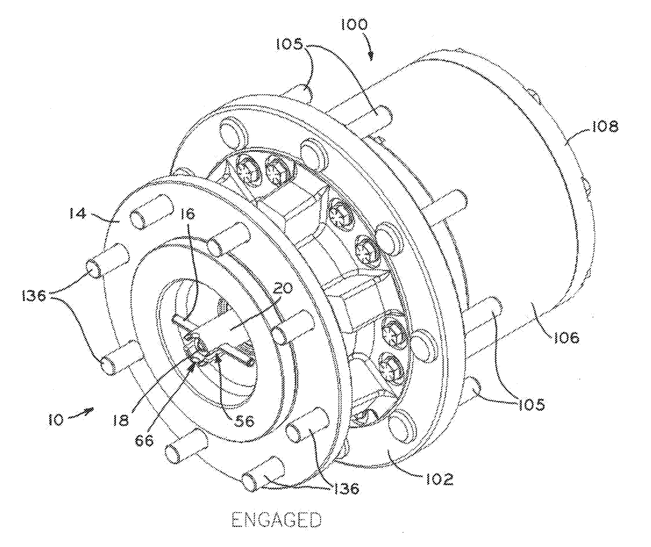
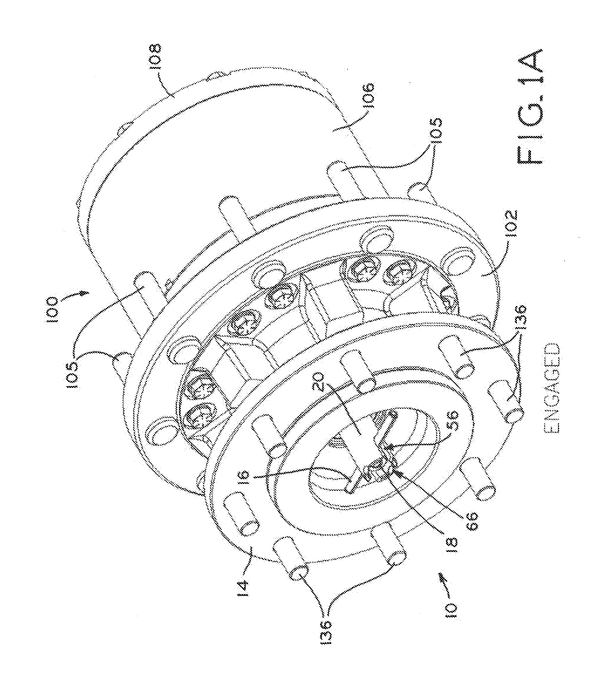
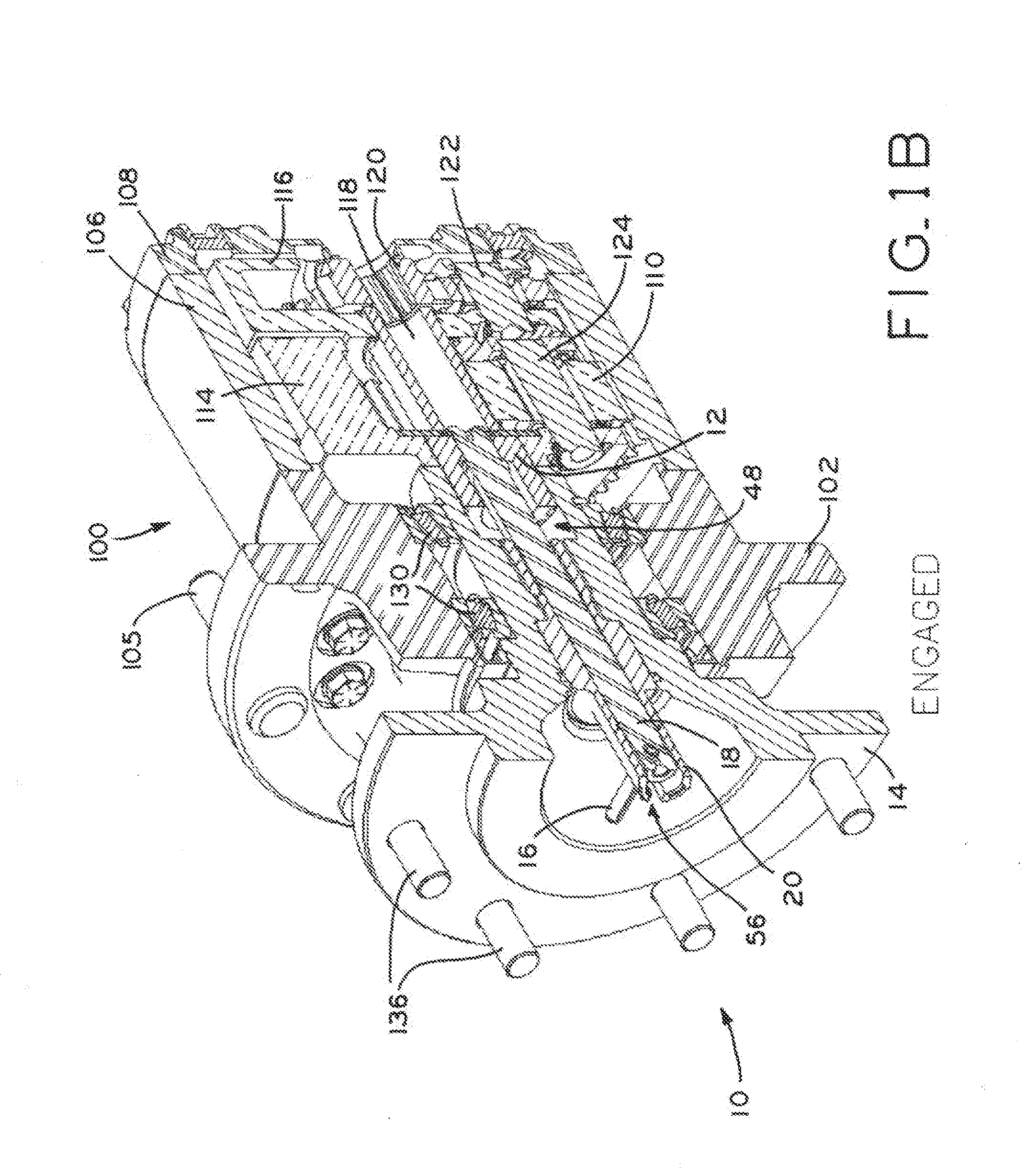
[0037]The present disclosure provides a drive unit disconnect mechanism 10 configurable between an engaged position (FIGS. 1A-1C), a “handle-disengaged” position (FIG. 2A-2C), and a “screw-disengaged” position (FIGS. 3A-3C). In the engaged configuration, coupling gear 12 of mechanism 10 rotationally fixes output hub 14 to planetary gear transmission assembly 101 of drive unit 100 (FIGS. 1B and 1C, described in detail below).
[0038]In the handle-disengaged position, handle 16 is used to draw inner disconnect shaft 18 out of outer disconnect shaft 20, so that coupling gear 12 is drawn into output hub 14 and fully disengages from planetary transmission assembly 101 of drive unit 100 (FIGS. 2B and 2C). As best shown in FIG. 2A, visual indication of the handle-disengaged configuration is provided by inner disconnect shaft 18 protruding from outer disconnect shaft 20 and handle 16 being out of alignment with slots 56 formed in outer shaft 20.
[0039]In the screw-disengaged configuration, out...
PUM
 Abstract
Description
Claims
Application Information
 - R&D
- Intellectual Property
- Life Sciences
- Materials
- Tech Scout
- Unparalleled Data Quality
- Higher Quality Content
- 60% Fewer Hallucinations
Browse by: Latest US Patents, China's latest patents, Technical Efficacy Thesaurus, Application Domain, Technology Topic, Popular Technical Reports.
© 2025 PatSnap. All rights reserved.Legal|Privacy policy|Modern Slavery Act Transparency Statement|Sitemap|About US| Contact US: help@patsnap.com


