
Backpack Frame

a frame and backpack technology, applied in the field of backpack frame, can solve the problems of reducing the effective load a user can carry, difficult manufacturing and maintenance, and many different materials used in the same frame, and achieve the effect of decoupling the load from the wearer

Active Publication Date: 2012-02-09
KUIU INC
View PDF6 Cites 23 Cited by
  • Summary
  • Abstract
  • Description
  • Claims
  • Application Information

AI Technical Summary

Benefits of technology

[0009]One aspect of the invention relates to a backpack with a semi-internal frame. The backpack frame is of unitary construction and includes a mid-back portion with openings that allow independently positionable shoulder strap assemblies to be attached. A U-shaped lower back portion provides a connection point for a belt assembly. A pair of stay portions are adapted to rest within a backpack, support a backpack load, and dynamically store and release energy resiliently so as to decouple the load from the wearer. The stay portions begin parallel to one another at a point just above the mid-back portion and curve outward laterally as they extend downward. The backpack frame may have a general curvature to match that of the human back, and may be comprised of resin-impregnated materials, including selectively reinforced carbon fiber.

Problems solved by technology

These types of frames are simple to construct, as the tubes are simply welded together, but they are typically very heavy, and thus reduce the effective load that a user can carry.
Internal backpack frames are generally made to be lighter, but problems typically arise in making an internal frame that has a useful combination of strength and flexibility.
However, the problem is multifaceted, because there are some places in a backpack frame where strength and stiffness are warranted in order to properly support the backpack load.
However, conventional attempts to use many different materials in the same frame often become so complex that they are difficult to manufacture and maintain.

Method used


Image

  • Backpack Frame
  • Backpack Frame
  • Backpack Frame

Examples


Embodiment Construction

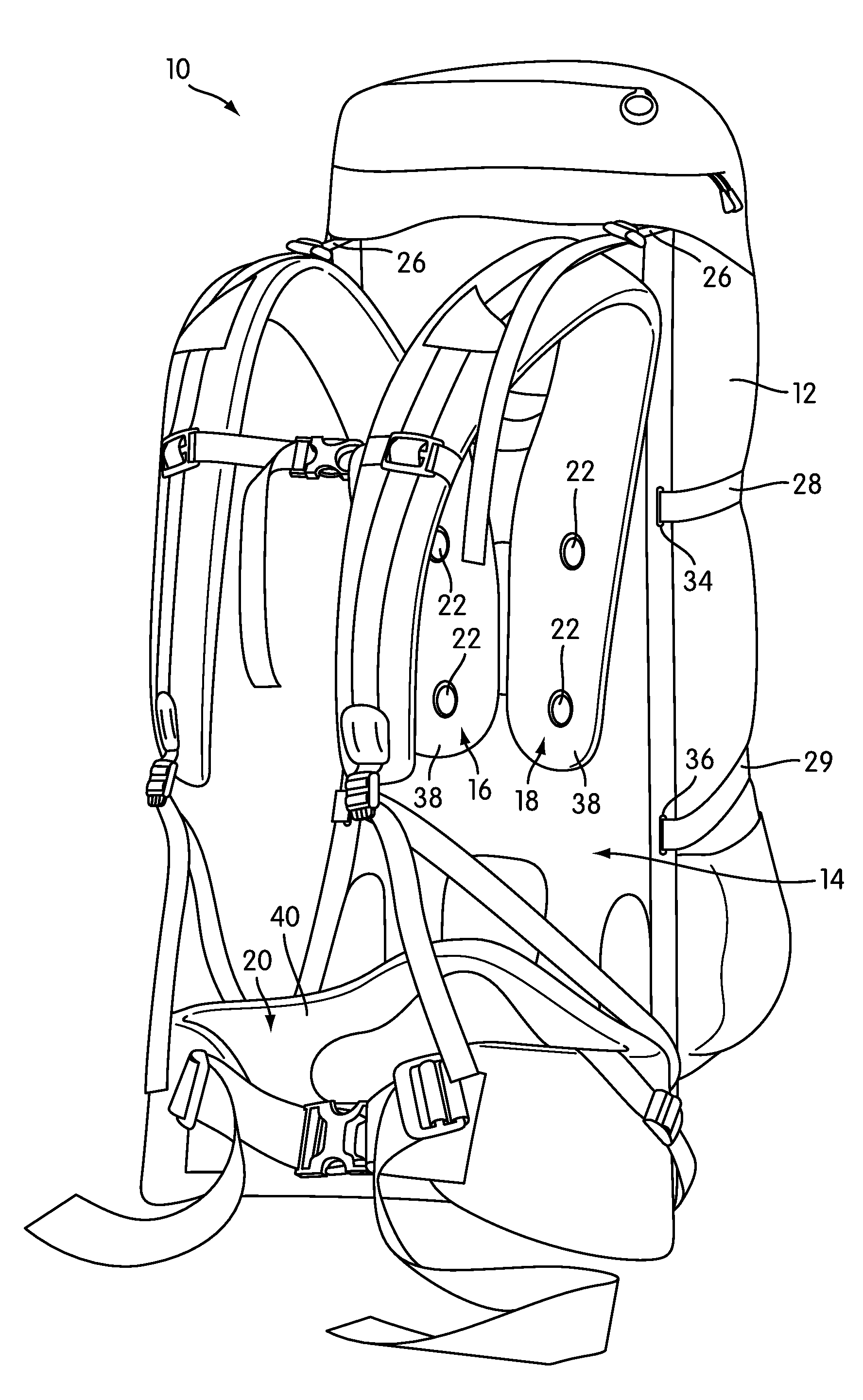
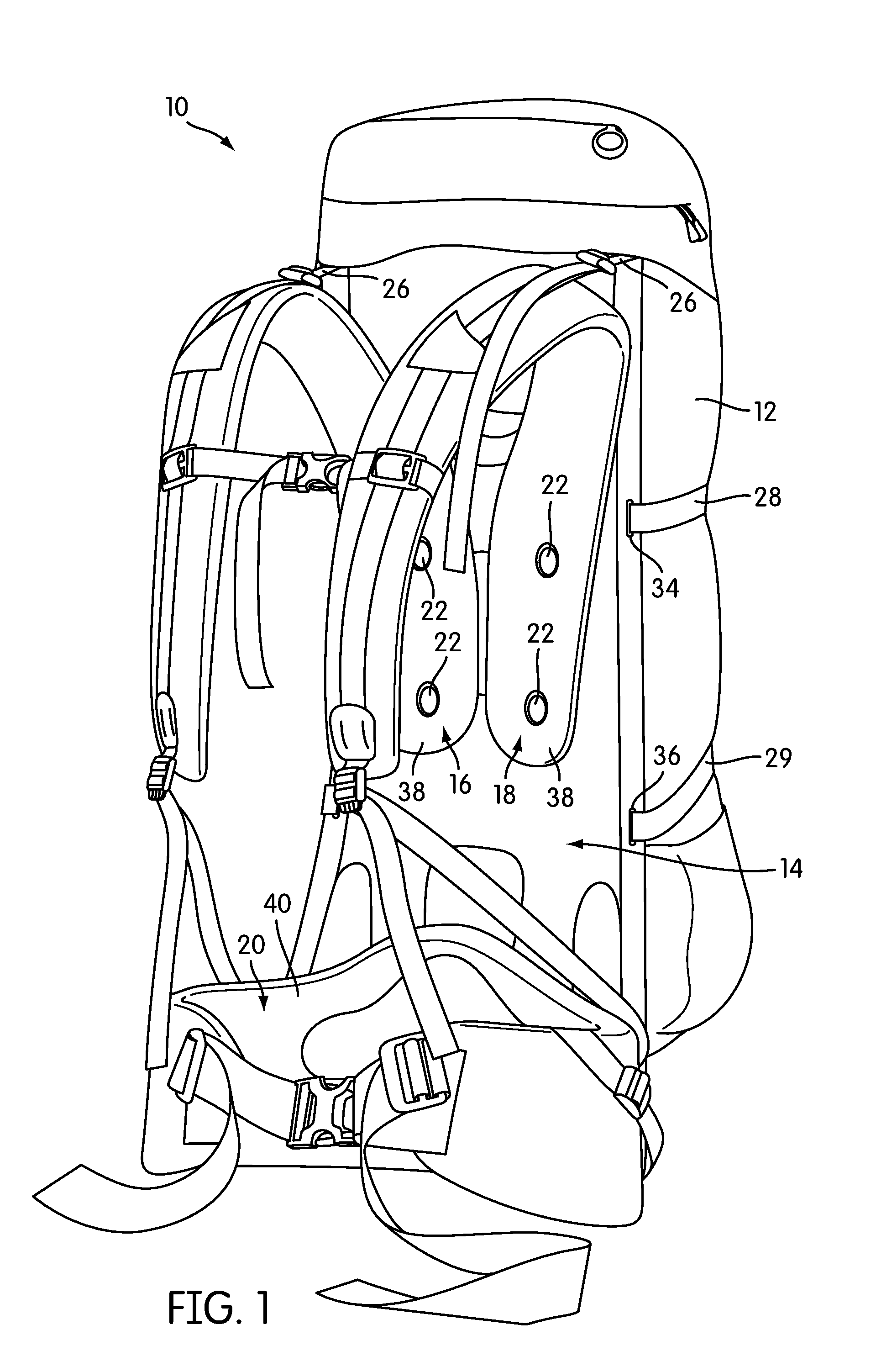
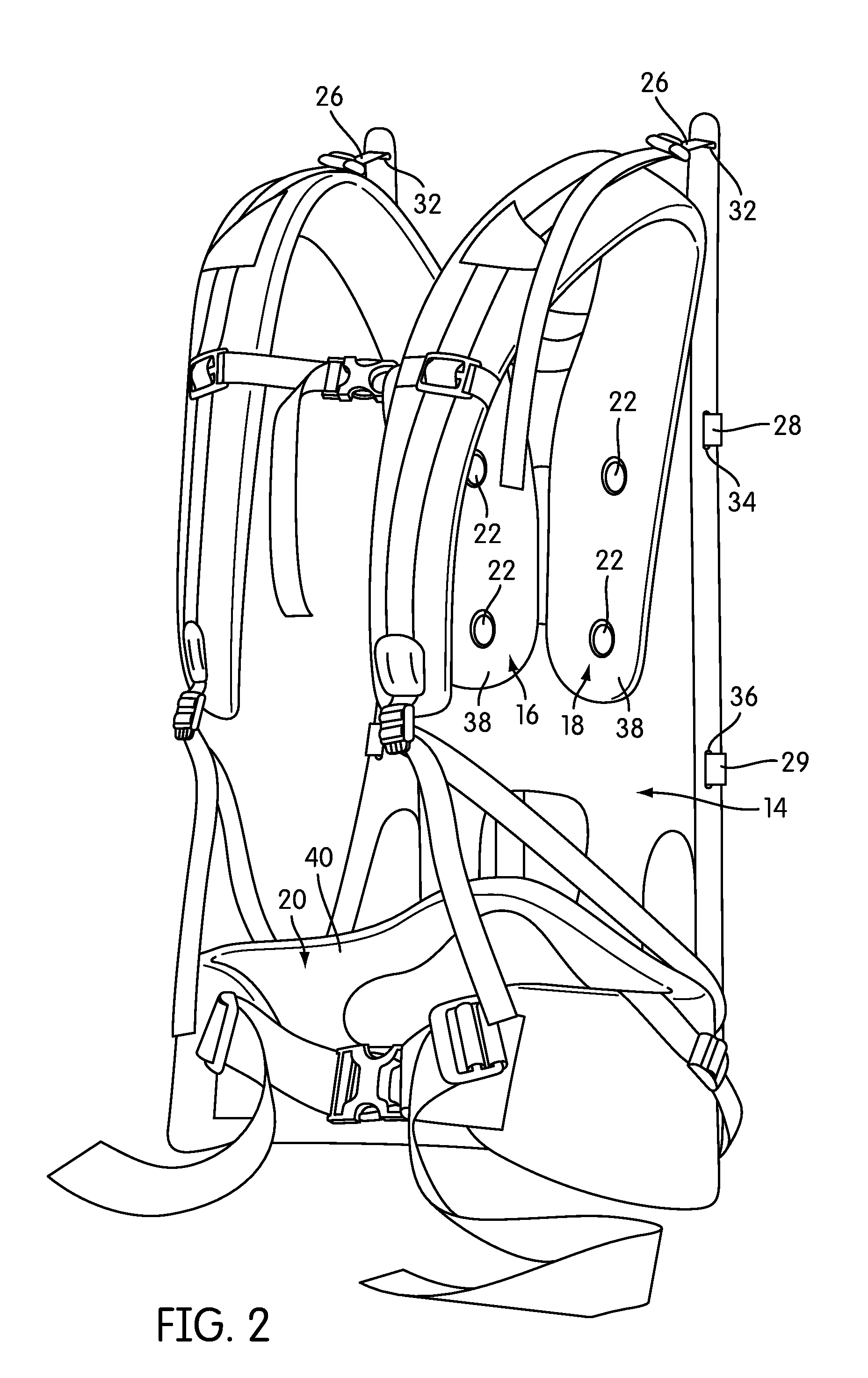
[0022]FIG. 1 is a rear perspective view of a backpack, generally indicated at 10, according to one embodiment of the invention. The backpack has a closeable storage volume 12 and a semi-internal frame, generally indicated at 14. As used in this description, the term “semi-internal” refers to the fact that in the illustrated embodiment, the frame 14 is at least partially exposed. However, the frame 14 need not necessarily be partially exposed in all embodiments, and may be completely internal.

[0023]The backpack 10 also includes three main load transfer points or nodes, at which the load of the backpack 10 is transferred to the wearer of the backpack 10: two independently adjustable and positionable shoulder strap assemblies 16, 18 and a belt assembly 20. The shoulder strap assemblies 16, 18 and belt assembly 20 attach to the frame 14 using fasteners 22, 24. As will be described below in more detail, the shoulder strap assemblies 16, 18 attach to the frame 14 along respective sliding ...


PUM

PropertyMeasurementUnit
thickaaaaaaaaaa
interstitialaaaaaaaaaa
lengthsaaaaaaaaaa

Abstract

A backpack and frame are disclosed. The backpack frame is designed to be at least partially internal and is of unitary construction, most advantageously of a resin-impregnated material, such as resin-impregnated carbon fiber sheets with selective reinforcement by interstitial layers. The frame has a mid-back portion that includes openings for independently positionable shoulder straps and a lower back portion that provides for a rotatable connection to a belt assembly. A pair of curved stay portions is contiguous with the mid-back portion of the frame and curves outwardly as the stay portions extend downwardly. The frame is preferably curved to match the curvature of the human back. The backpack frame is lightweight and by use of composite materials can provide strength as well as selective flexibility to suspend the load of the backpack and decouple it from the movements of the wearer.

Description

CROSS-REFERENCE TO RELATED APPLICATIONS[0001]This application claims priority to U.S. Provisional Patent Application No. 61 / 365,097, filed Jul. 16, 2010. The contents of that application are incorporated by reference in their entirety.BACKGROUND OF THE INVENTION[0002]1. Field of the Invention[0003]The invention relates to frames for backpacks and knapsacks.[0004]2. Description of Related Art[0005]Many backpacks and knapsacks have rigid or semirigid frames that act to suspend the backpack load and distribute it more evenly to the wearer's body. Some frames also allow a user to secure or cinch gear to his or her back more easily than with a backpack alone. Backpack frames may be either internal to the backpack or external to it.[0006]Traditionally, external backpack frames have been made of metal tubes, such as aluminum or steel tubes. These types of frames are simple to construct, as the tubes are simply welded together, but they are typically very heavy, and thus reduce the effectiv...

Claims


Application Information

Patent Timeline
Patent Type & Authority Applications(United States)
IPC IPC(8): A45F4/02B23P19/04
CPCA45F3/04A45F3/10Y10T29/49838A45F3/08A45F2003/045A45F3/047
Inventor HAIRSTON, JASONWEST, ZACHARY D.
Owner KUIU INC
Learn More