Al technical title is built by PatSnap Al team. It summarizes the technical point description of the patent document.
a kinesthetic control system and air-vehicle technology, applied in the field of augmented kinesthetic control systems, can solve the problems of limited weight and subsequent utility of the equipmen
Active Publication Date: 2012-02-09
AEROFEX
View PDF16 Cites 28 Cited by
Summary
Abstract
Description
Claims
Application Information
AI Technical Summary
This helps you quickly interpret patents by identifying the three key elements:
Problems solved by technology
Method used
Benefits of technology
Problems solved by technology
Although a variety of flying crafts have been designed which employ kinesthetic control systems, their weight and subsequent utility are limited.
Method used
Image
Click on the blue label to locate the original text in one second.
Reading with bidirectional positioning of images and text.
Examples
Embodiment Construction
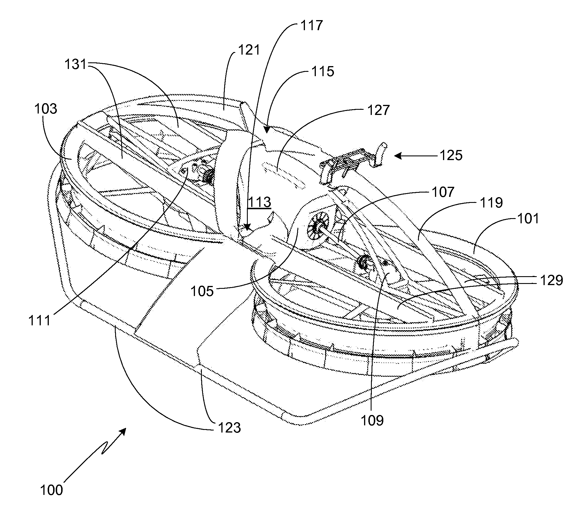
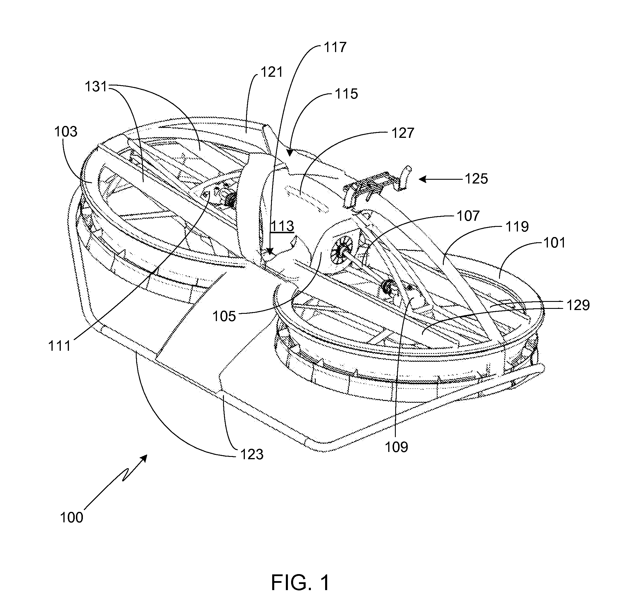
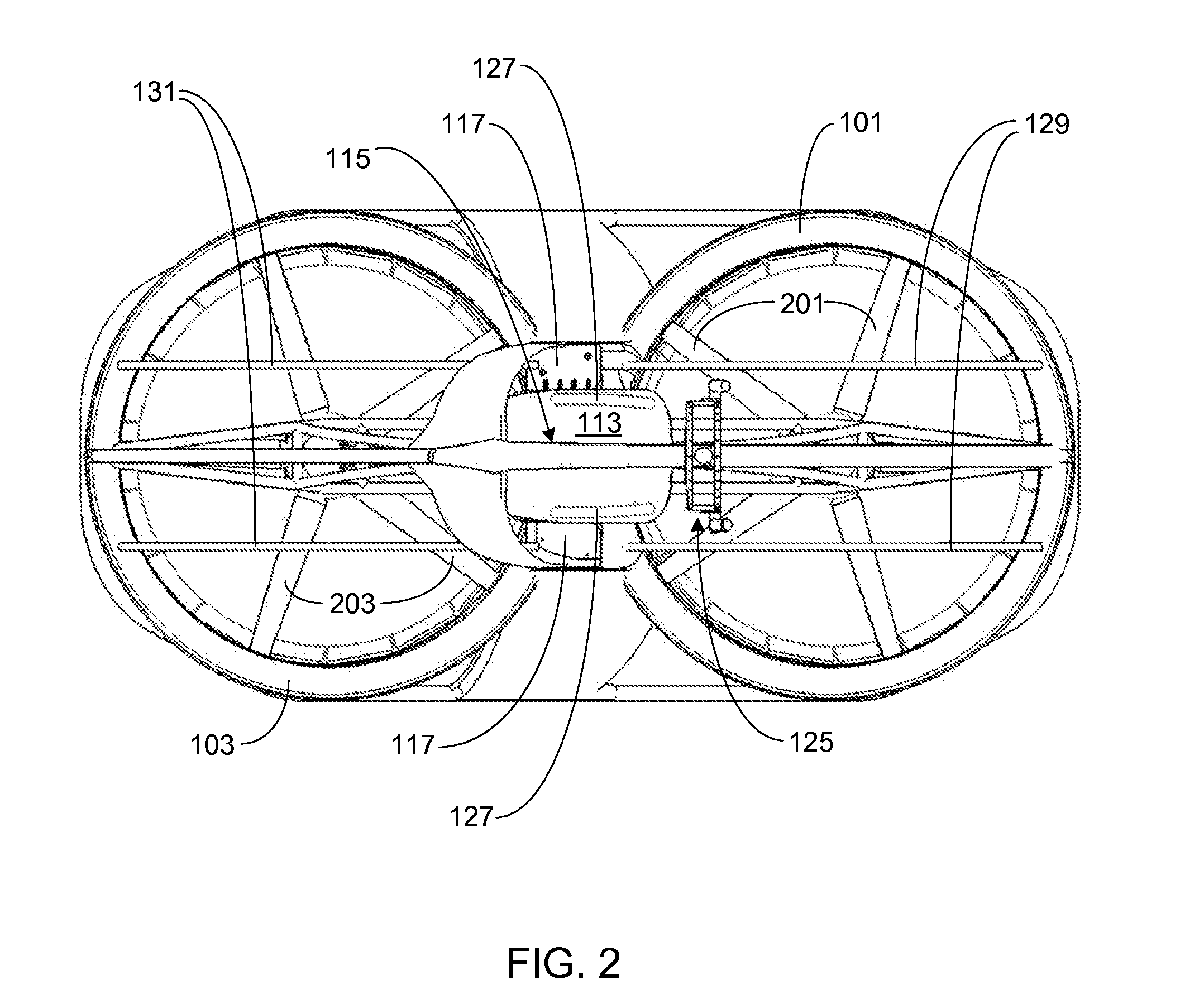
[0065]In the following text, the terms “center-of-gravity” and “CG” may be used interchangeably. Similarly, the terms “propeller” and “fan” may be used interchangeably herein. Note that identical element symbols used on multiple figures refer to the same component, or components of equal functionality. Additionally, the accompanying figures are only meant to illustrate, not limit, the scope of the invention and should not be considered to be drawn to scale.
[0066]The preferred embodiment of the present invention is comprised of three subsystems; a plurality of peripheral control ejectors that are primarily used to provide pitch and roll control, a set of longitudinal control surfaces that are primarily used for yaw control, and a pilot interface. Following a brief summary of the overall system, each of these subsystems will be described in detail. It will be appreciated by those of skill in the art that while these subsystems are preferably used in a combined system, each subsystem m...
PUM
Abstract
A lift platform with a kinesthetic control system that is coupled to means for altering air flow through the first and second longitudinally-spaced ducts comprising the lift platform is provided. The control system includes a control handle bar with left and right hand grips, and first and second control roll bars located on either side of the lift platform's central cowling. Forward / rearward movement of the control handle bar from a neutral position generates nose-down / nose-up pitching moments, respectively; counterclockwise / clockwise movement of the control handle bar from the neutral position generates counterclockwise rotation / clockwise rotation of the lift platform about a lift platform vertical centerline; and left movement / right movement of the control roll bars generates left roll / right roll moments about the lift platform roll axis.
Description
CROSS-REFERENCE TO RELATED APPLICATION[0001]This application is a continuation-in-part of U.S. patent application Ser. No. 11 / 900,147, filed 10 Sep. 2007, which claims the benefit of the filing date of U.S. Provisional Patent Application Ser. No. 60 / 848,258, filed 28 Sep. 2006, the disclosures of which are incorporated herein by reference for any and all purposes. This application is also a continuation-in-part of U.S. patent application Ser. No. 12 / 793,590, filed 3 Jun. 2010, which claims the benefit of the filing date of U.S. Provisional Patent Application Ser. No. 61 / 342,210, filed 10 Apr. 2010, the disclosures of which are incorporated herein by reference for any and all purposes. This application claims the benefit of the filing date of U.S. Provisional Patent Application Ser. Nos. 61 / 455,821, filed 27 Oct. 2010, 61 / 571,509, filed 25 Jun. 2011, 61 / 574,134, filed 28 Jul. 2011, and 61 / 575,227, filed 17 Aug. 2011, the disclosures of which are incorporated herein by reference for a...
Claims
Application Information
Patent Timeline
Application Date:The date an application was filed.
Publication Date:The date a patent or application was officially published.
First Publication Date:The earliest publication date of a patent with the same application number.
Issue Date:Publication date of the patent grant document.
PCT Entry Date:The Entry date of PCT National Phase.
Estimated Expiry Date:The statutory expiry date of a patent right according to the Patent Law, and it is the longest term of protection that the patent right can achieve without the termination of the patent right due to other reasons(Term extension factor has been taken into account ).
Invalid Date:Actual expiry date is based on effective date or publication date of legal transaction data of invalid patent.
Patent Type & Authority Applications(United States)