Pipe Connection Having A Flow Counting Function

a technology of flow counting and pipe connection, which is applied in the direction of liquid/fluent solid measurement, volume metering, instruments, etc., can solve the problems of easy consumption of water resources, and achieve the effect of saving water resources and regulating water flow easily and quickly

Active Publication Date: 2012-02-16
SHIH PAO YUN
View PDF4 Cites 8 Cited by
  • Summary
  • Abstract
  • Description
  • Claims
  • Application Information

AI Technical Summary

Benefits of technology

[0008]According to the primary advantage of the present invention, the pipe connection can calculate and indicate the water flow rate in the pipe so that when the flow rate of the output water from the pipe reaches a preset value, the user can shut the water flow to regulate the water flow so as to save the water resource.
[0009]According to another advantage of the present invention, the flow rate of the water is directly indicated on the display of the circuit board so that the user can regulate the water flow easily and quickly.
[0010]Further benefits and advantages of the present invention will become apparent after a careful reading of the detailed description with appropriate reference to the accompanying drawings.
[0011]FIG. 1 is a perspective view of a pipe connection in accordance with the preferred embodiment of the present invention.
[0012]FIG. 2 is an exploded perspective view of the pipe connection as shown in FIG. 1.
[0013]FIG. 3 is a front cross-sectional view of the pipe connection as shown in FIG. 1.

Problems solved by technology

However, the conventional pipe connection cannot calculate the water flow rate in the pipe so that the user cannot regulate water flow exactly, thereby easily consuming the water resource.

Method used


Image

  • Pipe Connection Having A Flow Counting Function
  • Pipe Connection Having A Flow Counting Function
  • Pipe Connection Having A Flow Counting Function

Examples


Embodiment Construction

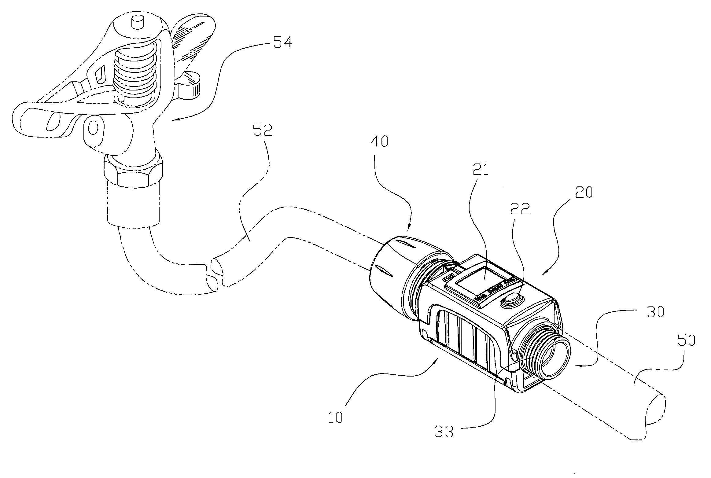
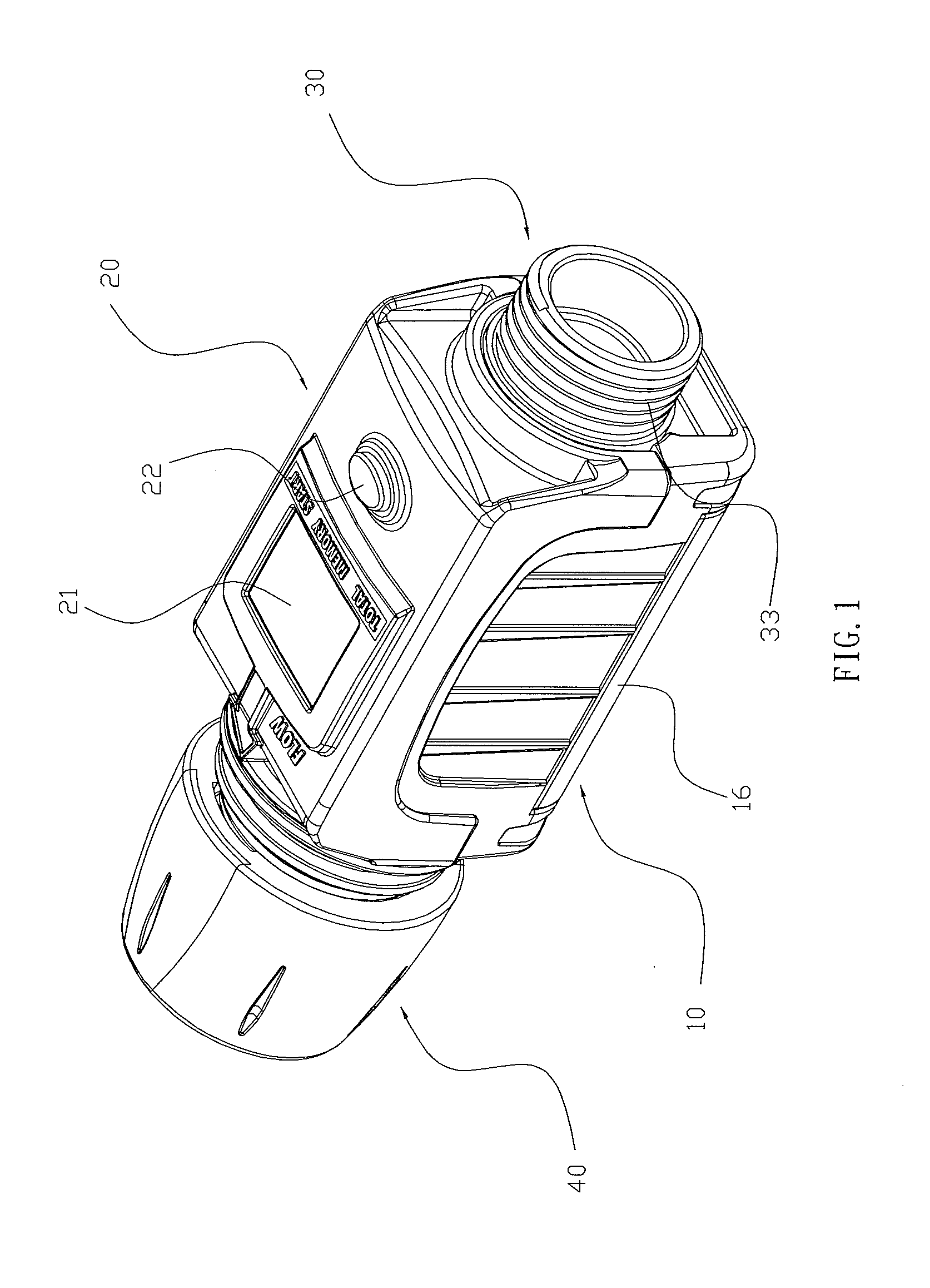
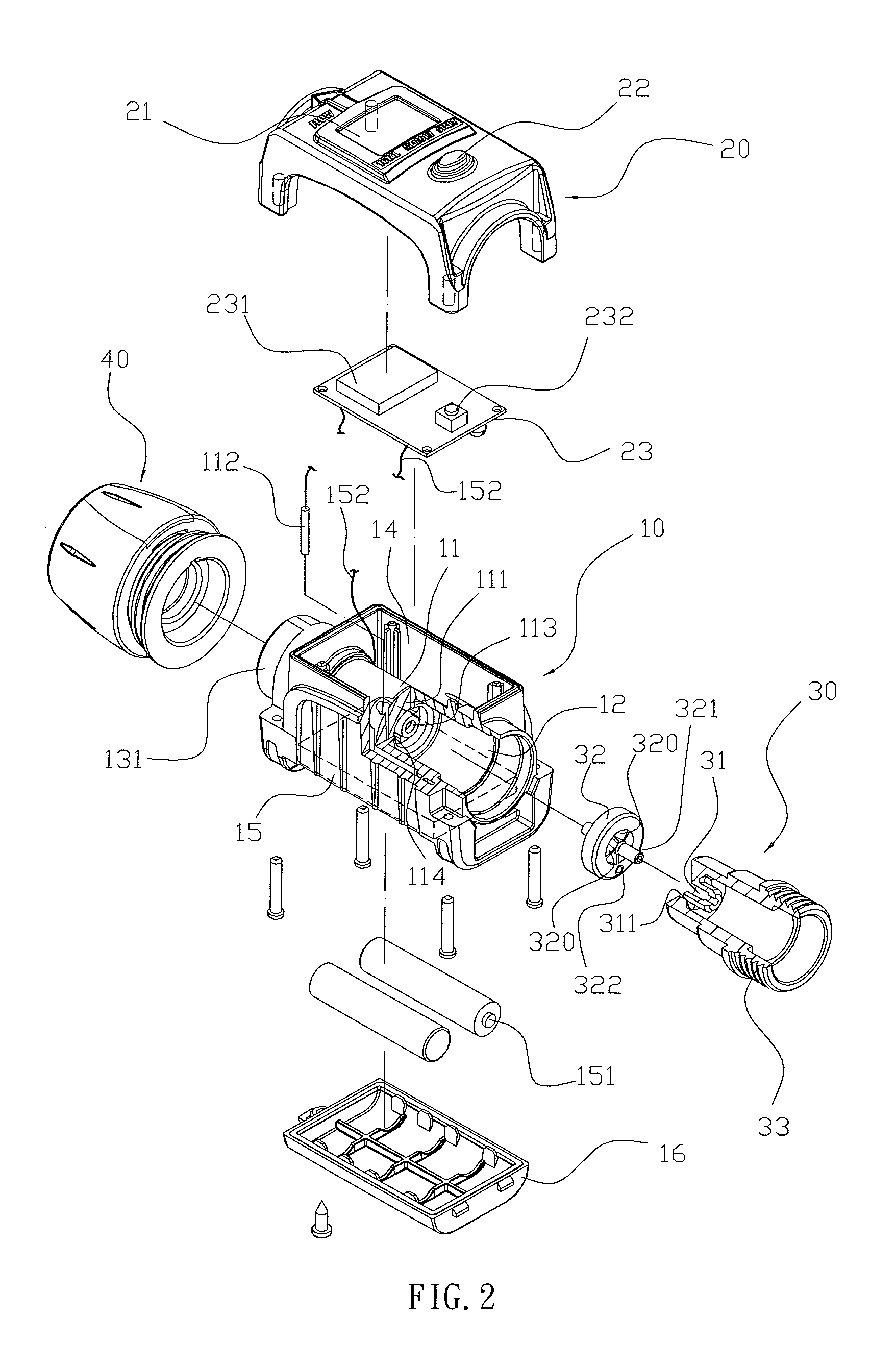
[0021]Referring to the drawings and initially to FIGS. 1-4, a pipe connection in accordance with the preferred embodiment of the present invention comprises a main body 10, an inner sleeve 11 mounted in the main body 10 and having a first end formed with a receiving chamber 12, a second end formed with a flow channel 13 and a mediate portion provided with a separation wall 111 connected between the receiving chamber 12 and the flow channel 13, a water inlet connector 30 mounted on a first end of the main body 10 and connected to the receiving chamber 12 of the inner sleeve 11, a water outlet connector 40 mounted on a second end of the main body 10 and connected to the flow channel 13 of the inner sleeve 11, a circuit board 23 mounted on the main body 10, a control panel 20 mounted on the main body 10 and aligning with the circuit board 23, at least one battery 151 mounted on the main body 10 and electrically connected with the circuit board 23 by at least one electric wire 152 to su...


PUM


Abstract

A pipe connection includes a main body, an inner sleeve, a water inlet connector, a water outlet connector, a circuit board, a control panel, at least one battery, a magnetically activated detector, an impeller, and a magnetic member. In operation, when the water flows through the impeller, the impeller is rotated, and the magnetic member is moved to pass by the detector intermittently so that the detector can transmit a detected signal to the circuit board which can calculate the rotation speed of the magnetic member so as to obtain the water flow rate. Thus, the pipe connection can calculate and indicate the water flow rate in the pipe so that when the flow rate of the output water from the pipe reaches a preset value, the user can shut the water flow to regulate and save the water flow.

Description

BACKGROUND OF THE INVENTION[0001]1. Field of the Invention[0002]The present invention relates to a connecting device and, more particularly, to a pipe connection to connect two water pipes.[0003]2. Description of the Related Art[0004]A conventional pipe connection has a first end connected with a first pipe which is connected with a water source, such as a faucet and the like, and has a second end connected with a second pipe which is connected with a water outlet device, such as a sprinkler, sprayer and the like. Thus, water from the first pipe in turn flows through the pipe connection into the second pipe and is injected outward from the water outlet device for use with a user. However, the conventional pipe connection cannot calculate the water flow rate in the pipe so that the user cannot regulate water flow exactly, thereby easily consuming the water resource.BRIEF SUMMARY OF THE INVENTION[0005]In accordance with the present invention, there is provided a pipe connection, compr...

Claims


Application Information

Patent Timeline
Patent Type & Authority Applications(United States)
IPC IPC(8): F16L25/00G01F1/56
CPCG01F1/115G01F15/003G01F15/005
Inventor SHIH, PAO-YUN
Owner SHIH PAO YUN
Why Eureka
Try Eureka