
Surgical instrument system and method for providing retraction and vertebral distraction

a technology of surgical instruments and distraction, applied in the field of surgical instruments for providing retraction and vertebral distraction, can solve the problems of additional approach challenges, limited surgical exposure, and difficult procedures for surgeons to perform

Active Publication Date: 2012-02-16
DIETZE JR DONALD DAVID +1
View PDF21 Cites 65 Cited by
  • Summary
  • Abstract
  • Description
  • Claims
  • Application Information

AI Technical Summary

Benefits of technology

[0012]The foregoing summary, as well as the following detailed description of preferred embodiments of the invention, will be better understood when read in conjunction with the appended drawings. For the purpose of illu...

Problems solved by technology

However, ELIF often presents additional approach challenges over the TLIF procedure.
When performing minimally invasive procedures like the TLIF or ELIF procedures, surgical exposure is sometimes limited by the retractor utilized for a procedure and such procedures can be difficult for surgeons to perform through the relatively small surgical channels that are created by such existing retractors.
The table mount can also clutter the surgical field by obstructing access to the incision.
Surgical procedures conducted through a minimally invasive working channel for TLIF and ELIF procedures can be challenging due to space restrictions, confinement and limitations of prior art retractors.
Existing retractors may also be limited to specific access angles to the surgical site.
TLIF and ELIF procedures can also be complicated by prior art retractors and table mounts “cluttering” the surgical field.
Retractor table mount hardware is often cumbersome, requires significant set-up and impedes visibility to the surgical site and through the working channel.

Method used


Image

  • Surgical instrument system and method for providing retraction and vertebral distraction
  • Surgical instrument system and method for providing retraction and vertebral distraction
  • Surgical instrument system and method for providing retraction and vertebral distraction

Examples


Embodiment Construction

[0031]Certain terminology is used in the following description for convenience only and is not limiting. The words “right,”“left,”“lower,” and “upper” designate directions in the drawings to which reference is made. The words “inwardly” or “distally” and “outwardly” or “proximally” refer to directions toward and away from, respectively, the geometric center or orientation of the surgical instrument, implants and / or related parts thereof. The words, “anterior,”“posterior,”“superior,”“inferior,”“lateral,”“medial,”“cranial,”“cephalad,”“caudal,”“caudad” and related words and / or phrases designate preferred positions and orientations in the human body or the patient to which reference is made and are not meant to be limiting. The terminology includes the above-listed words, derivatives thereof and words of similar import.

[0032]Referring to FIGS. 1-3, preferred embodiments of the present invention are directed to an instrument 1 for spinal surgery for retracting soft tissue and mounting be...


PUM


Abstract

An instrument for spinal surgery for retracting soft tissue and mounting between a superior spinous process and an inferior spinous process includes a relatively rigid frame, a first retractor blade mounted to the frame and a distractor element movably mounted to the frame. The distractor element has a body, a proximal end and a distal end. The distractor element has a thickness and a length. The distractor element is configured for mounting between the superior and inferior spinous processes in a working configuration. The distractor element is generally tapered at the distal end in an insertion configuration. The instrument also includes an insertion shaft attached to the proximal end and a first shaft joint mounted between the frame and the insertion shaft.

Description

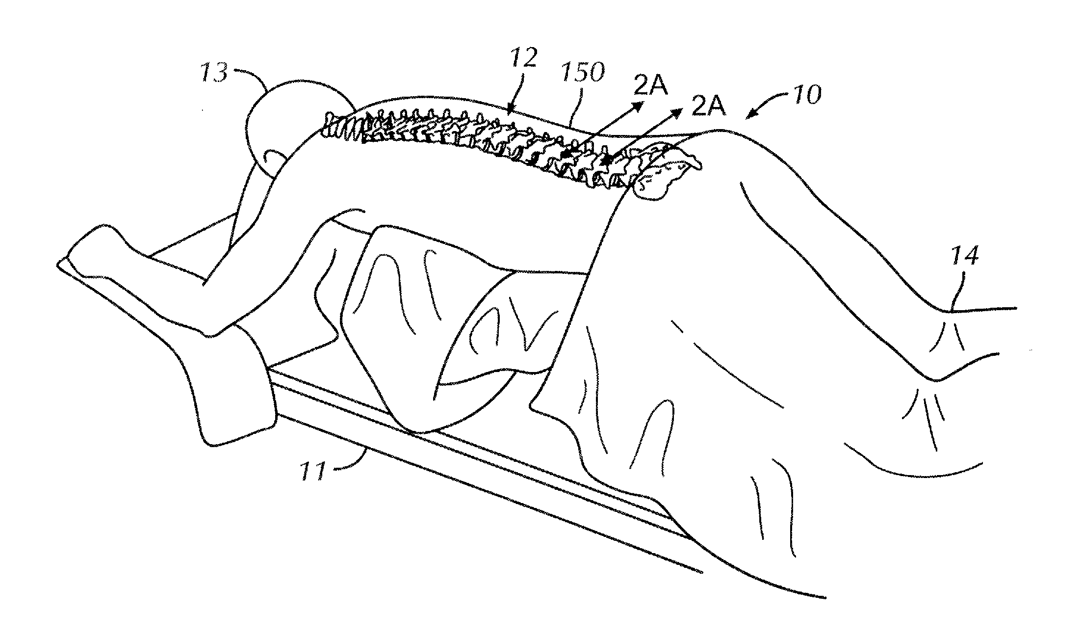
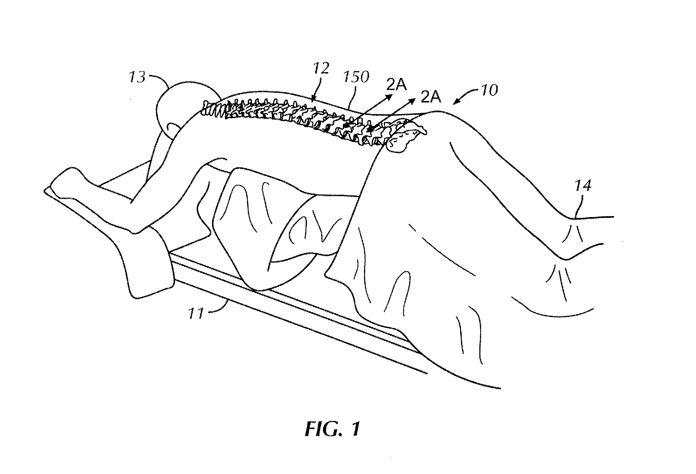
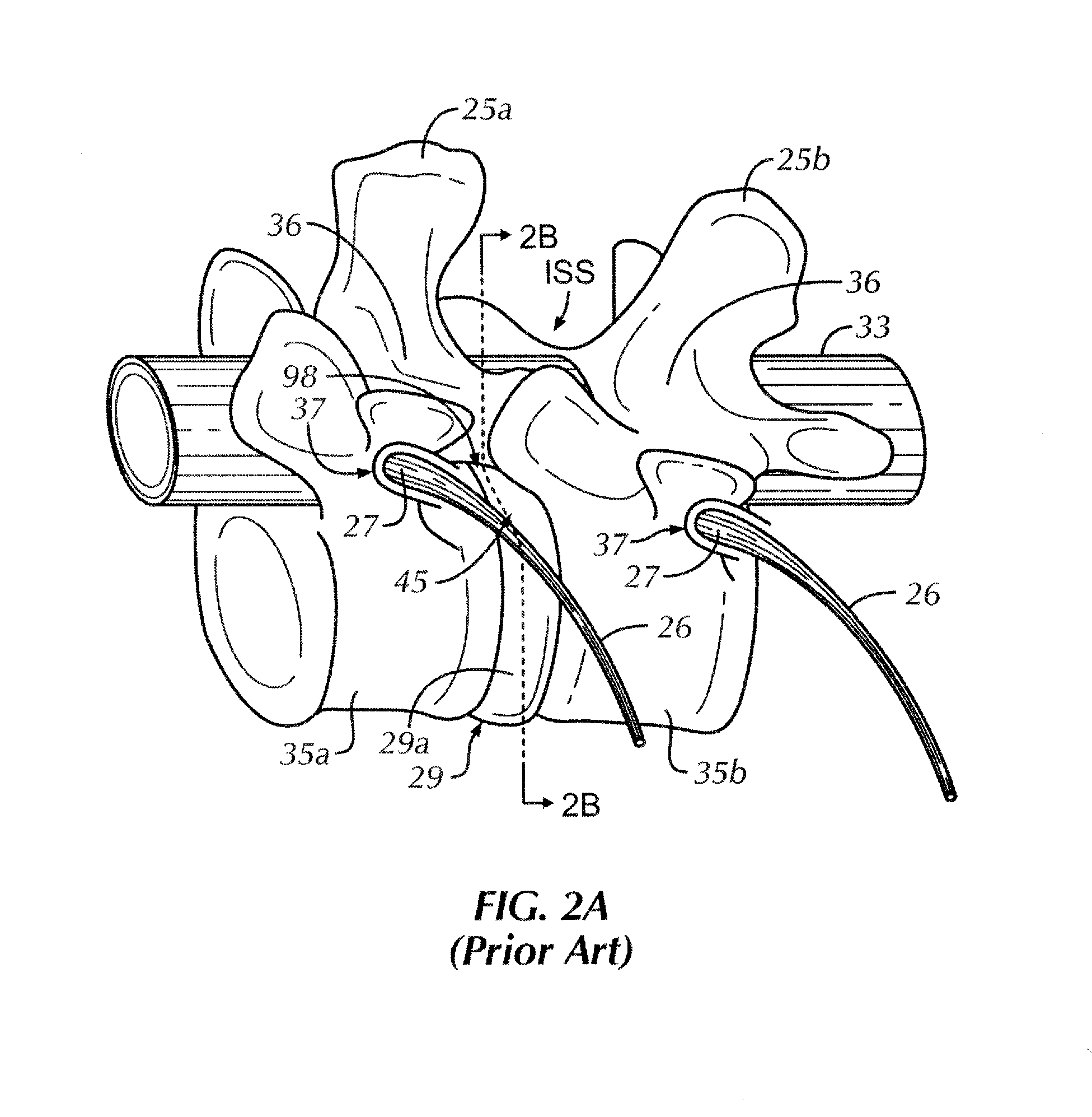
CROSS-REFERENCE TO RELATED APPLICATIONS[0001]This application is entitled to priority pursuant to 35 U.S.C. §119 (e) to U.S. Provisional Patent Application No. 61 / 373,885, filed Aug. 16, 2010, which is incorporated by reference herein in its entirety.BACKGROUND OF THE INVENTION[0002]Invasive surgical procedures require a surgeon to create an incision in the patient's skin 150 in order to access a surgical site within the patient's body where the surgery is performed. A tissue retractor can be used during the surgical procedure and, in particular, during minimally invasive surgical procedures to temporarily displace tissue and create a relatively small working channel to the surgical site. The working channel of minimally invasive surgical procedures is typically smaller than working channels of traditional open procedures. Such minimally invasive tissue retractors allow unobstructed or nearly unobstructed access to the target or surgical site while limiting the amount of dissection ...

Claims


Application Information

Patent Timeline
IPC IPC(8): A61B1/32
CPCA61B17/0206A61B17/025A61B17/0293A61B17/7065A61B2017/0262A61B2017/00915A61B2017/00946A61B2017/0256A61B2017/00557
Inventor DIETZE, JR., DONALD DAVIDBANKOSKI, BRIAN REED
Owner DIETZE JR DONALD DAVID
Learn More