Laundry machine

a technology for washing machines and clothes, applied in the field of laundry machines, can solve the problems of low damage to the clothes, difficulty in a specific type of washing machine to have advantages, and stretched clothes, etc., and achieve the effect of preventing occurrence and optimum performan

Active Publication Date: 2012-02-23
LG ELECTRONICS INC
View PDF4 Cites 35 Cited by
  • Summary
  • Abstract
  • Description
  • Claims
  • Application Information

AI Technical Summary

Benefits of technology

[0042]The laundry machine according to the present invention basically solves the problems of a conventional drum washing machine and a conventional pulsator washing machine.
[0043]More specifically, the present invention provides a new type of laundry machine having advantages of a drum washing machine and a pulsator washing machine.
[0044]Also, the present invention provides a laundry machine that is switched from a drum washing machine to a pulsator washing machine or from a pulsator washing machine to a drum washing machine according to user selection or optimum circumstance.
[0045]Also, the present invention provides a laundry machine wherein a tiling angle of a rotation shaft of a drum is changed as needed in a plurality of washing courses performed by rotating the drum or sub operations of each of the washing courses, thereby achieving optimum performance.
[0046]Also, the present invention provides a laundry machine that prevents occurrence of a children's accident.

Problems solved by technology

Also, washing is performed not by force of water but by lifting and dropping laundry, with the result that damage to the laundry is low.
In particular, the pulsator washing machine performs washing using force of water, with the result that laundry becomes tangled, and therefore, the laundry may be damaged, e.g., stretched.
Therefore, it is difficult for a specific type of washing machine to have advantages of other types of washing machines.
However, this washing machine also has disadvantages.
This is because an energy saving effect is not expected in a structure in which the rotation shaft of the drum is provided horizontally.

Method used


Image

  • Laundry machine
  • Laundry machine
  • Laundry machine

Examples


Embodiment Construction

[0056]Reference will now be made in detail to the preferred embodiments of the present invention, examples of which are illustrated in the accompanying drawings.

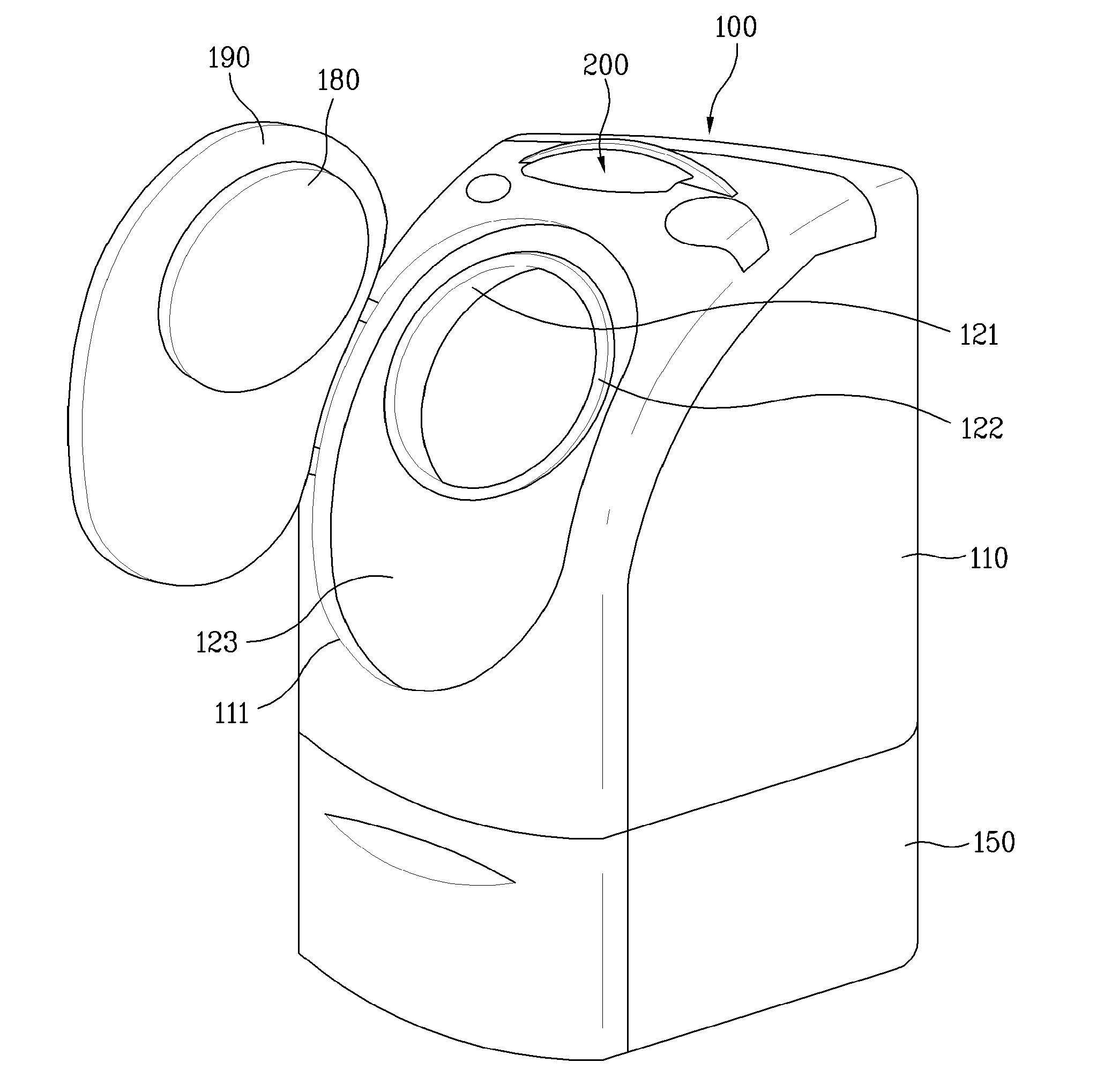
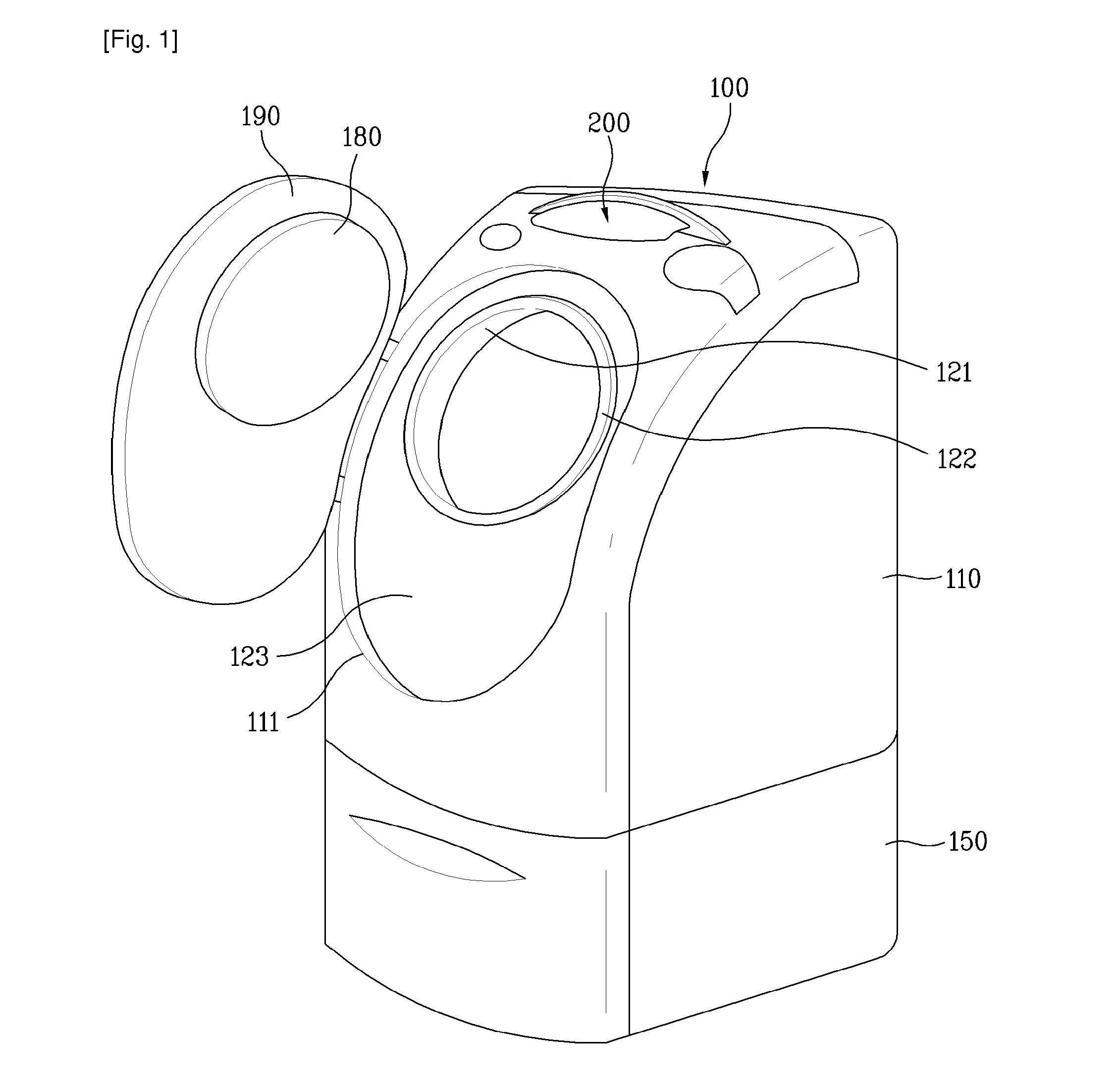
[0057]As shown in FIGS. 1 and 2, a laundry machine 100 according to an embodiment of the present invention includes a cabinet 110 forming the external appearance of the laundry machine 100.

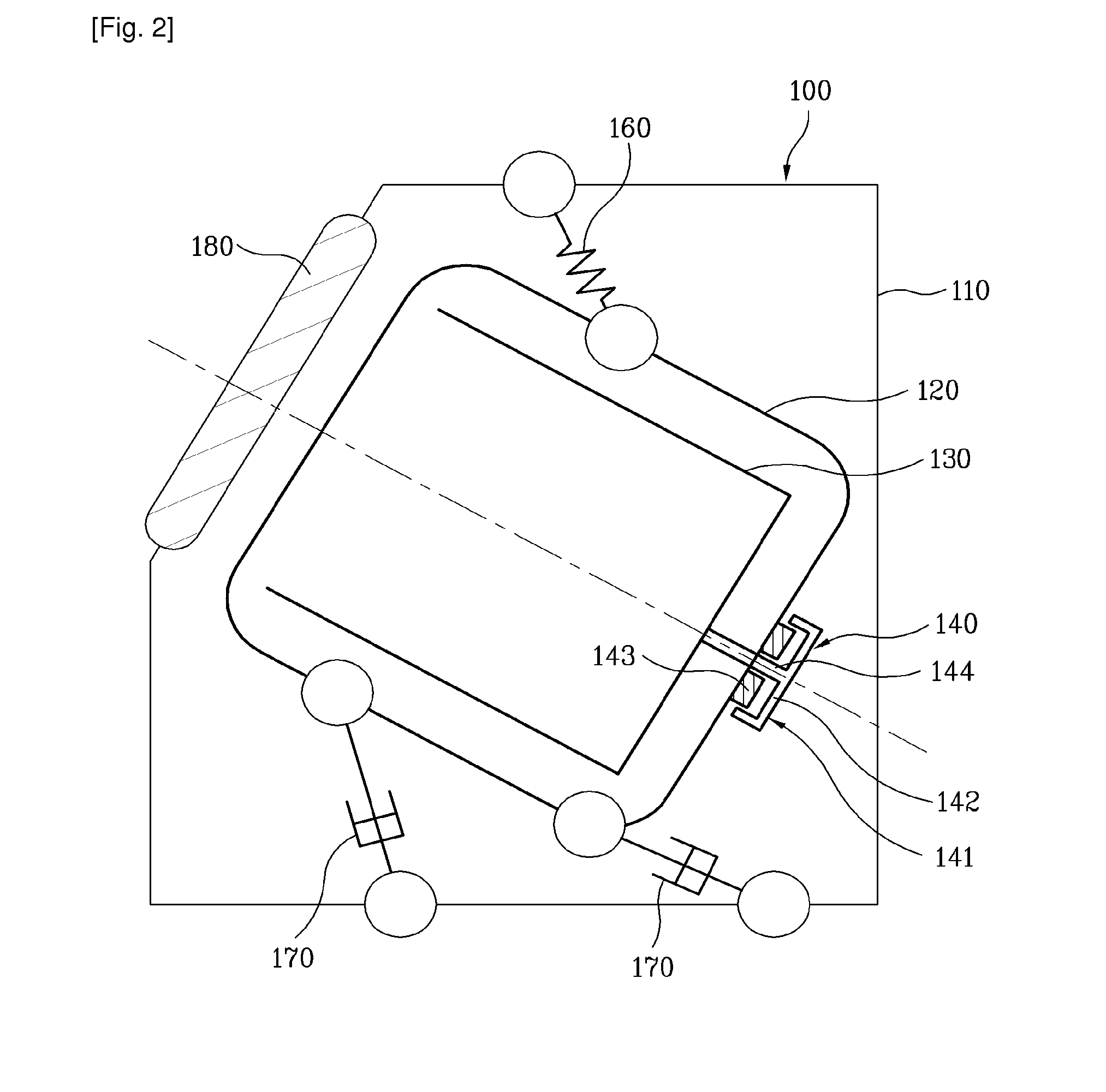
[0058]As shown in FIG. 2, a tub 120 is provided inside the cabinet 110. The tub 120 is configured to store wash water. A drum 130 is rotatably provided inside the tub 120. The drum 130 is a space to house laundry. In the drum 130, washing is performed using detergent and wash water.

[0059]Inside the cabinet 110 is provided a drive unit 140 to rotate the drum 130. The drive unit 140 includes a motor 141 and a drive shaft, i.e., a rotation shaft 144. The motor 141 is controlled by a controller (not shown) to rotate the drum 130 via the rotation shaft 144.

[0060]The motor 141 may include a rotor 142 and a stator 143. The rotor 142 may be an out...


PUM


Abstract

A laundry machine that treats laundry housed in a rotating drum is disclosed. The laundry machine includes a cabinet (110), a tub (120) provided in the cabinet (110) to store wash water, a drum (130) rotatably provided in the tub (120) to house laundry, an angle change device (170) to change a tilting angle of a rotation shaft (144) of the drum (130), and a controller to control an operation of the angle change device (170) and a rotating operation of the drum (130) in a plurality of rotation angle modes.

Description

TECHNICAL FIELD[0001]The present invention relates to a laundry machine, and more particularly, to a laundry machine that treats laundry housed in a rotating drum.BACKGROUND ART[0002]A laundry machine is a machine that washes or dries clothes. Representative examples of the laundry machine include a washing machine, a drying machine, and a washing and drying machine. On the other hand, the laundry machine may be classified as a drum type laundry machine that treats laundry housed in a rotating drum or a cabinet type laundry machine that treats laundry housed in a stationary space.[0003]Based on an angle of a rotation shaft of the rotating drum, the drum type laundry machine may be classified as a horizontal shaft laundry machine or a vertical shaft laundry machine.[0004]In the horizontal shaft laundry machine, the rotation shaft of the drum is provided approximately horizontally, and laundry is lifted and dropped with the rotation of the drum such that the laundry is treated. Of cou...

Claims


Application Information

Patent Timeline
Patent Type & Authority Applications(United States)
IPC IPC(8): D06F21/00D06F33/08D06F37/28D06F34/28
CPCD06F33/02D06F2232/00D06F2214/00D06F39/14D06F95/00D06F23/06D06F37/22D06F37/267D06F2101/20D06F2105/54D06F2101/00D06F34/28D06F2105/02D06F37/04D06F39/12
Inventor HONG, SANG WOOKCHANG, JAE WONPARK, SUN YOUNGKOO, BON KWONKANG, KI YOUNGKIM, JI HEE
Owner LG ELECTRONICS INC
Why Eureka
Try Eureka