Magnetic Connector

a technology of magnetic connectors and magnets, applied in the direction of permanent magnets, magnetic bodies, magnetic materials, etc., can solve the problems of significant inconvenience, difficult to separate the magnets with the fingers of both hands, and difficult to pick the same with thumb and index finger, so as to achieve the effect of preventing easy separation in the pulling direction

Inactive Publication Date: 2012-02-23
SEBERU PICO
View PDF13 Cites 76 Cited by
  • Summary
  • Abstract
  • Description
  • Claims
  • Application Information

AI Technical Summary

Benefits of technology

[0027]In order to enable the slide of one of the coupling pieces attracting each other with respect to the other with the fingers of only one hand so as to separate the one from the other, such slide is allowed and easy separation in the pulling direction may be prevented.

Problems solved by technology

Although the above-described conventional coupling device has an effect to prevent separation when the pulling force is applied in a longitudinal direction of the string body, this is significantly inconvenient when it is tried to release the connection.
Further, since the coupling device used in the necklace is much smaller than a finger pad, it is quite difficult to pick the same with a thumb and an index finger, for example, and it is difficult to pick both of the magnets with fingers of both hands to separate them from each other beyond expectation.
The difficulty is a disadvantage of the conventional coupling device.

Method used


Image

  • Magnetic Connector
  • Magnetic Connector
  • Magnetic Connector

Examples


first modified example

of this Embodiment

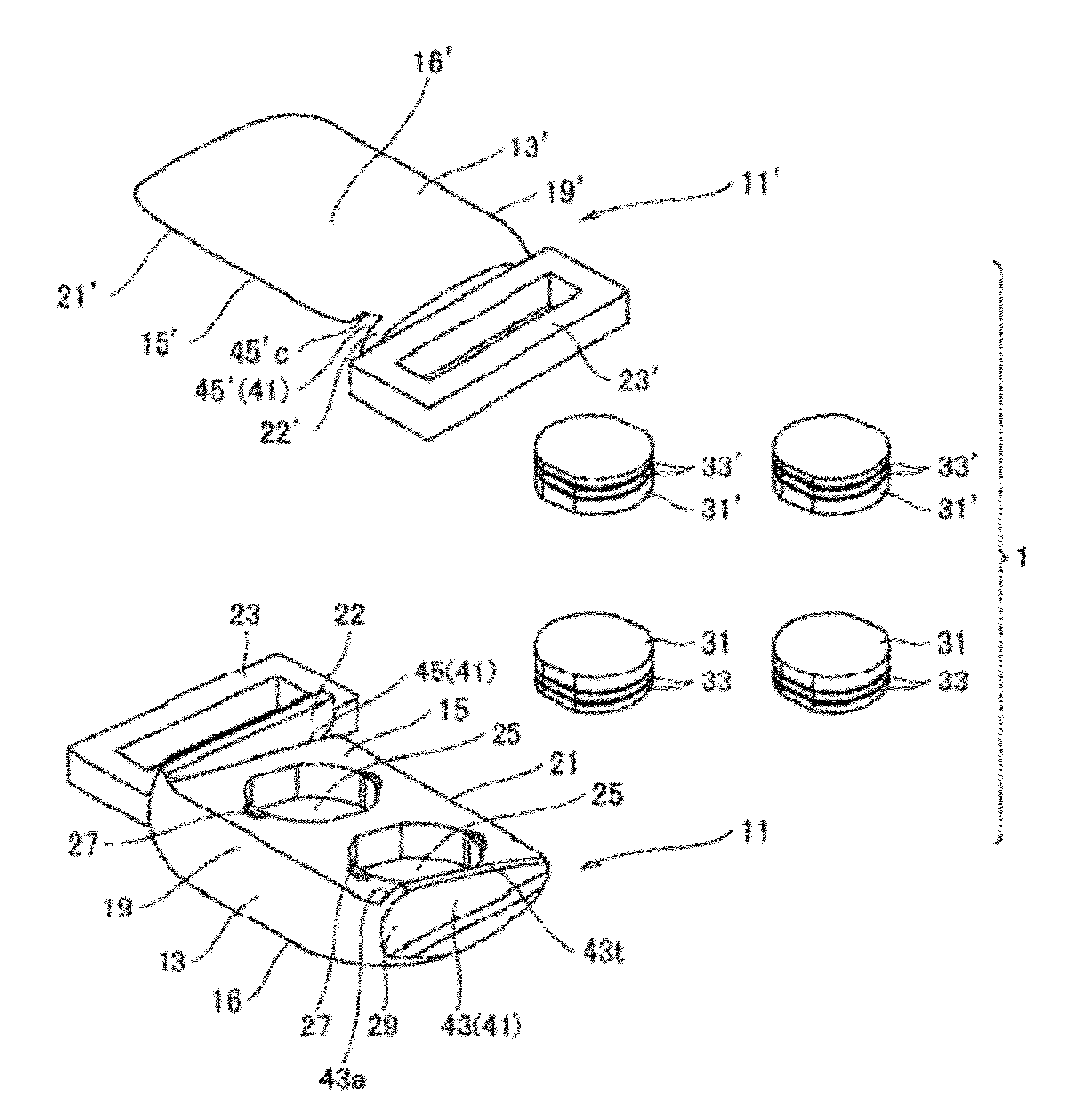
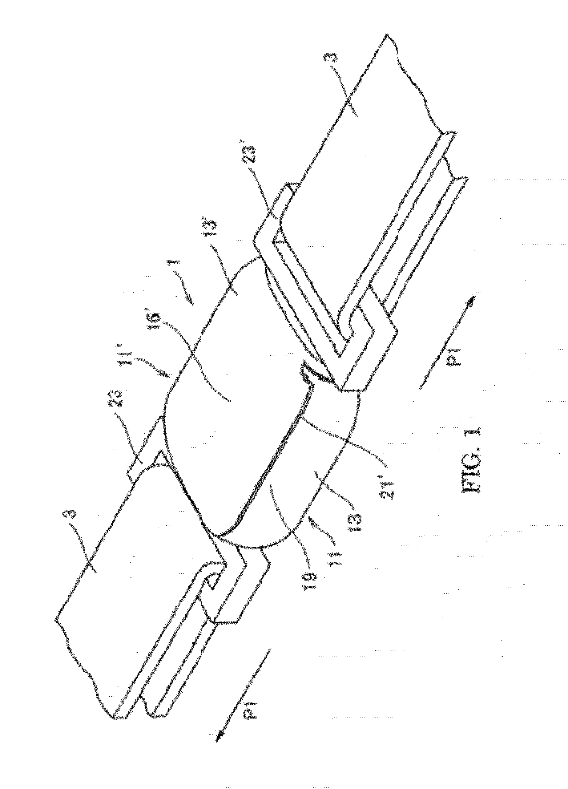
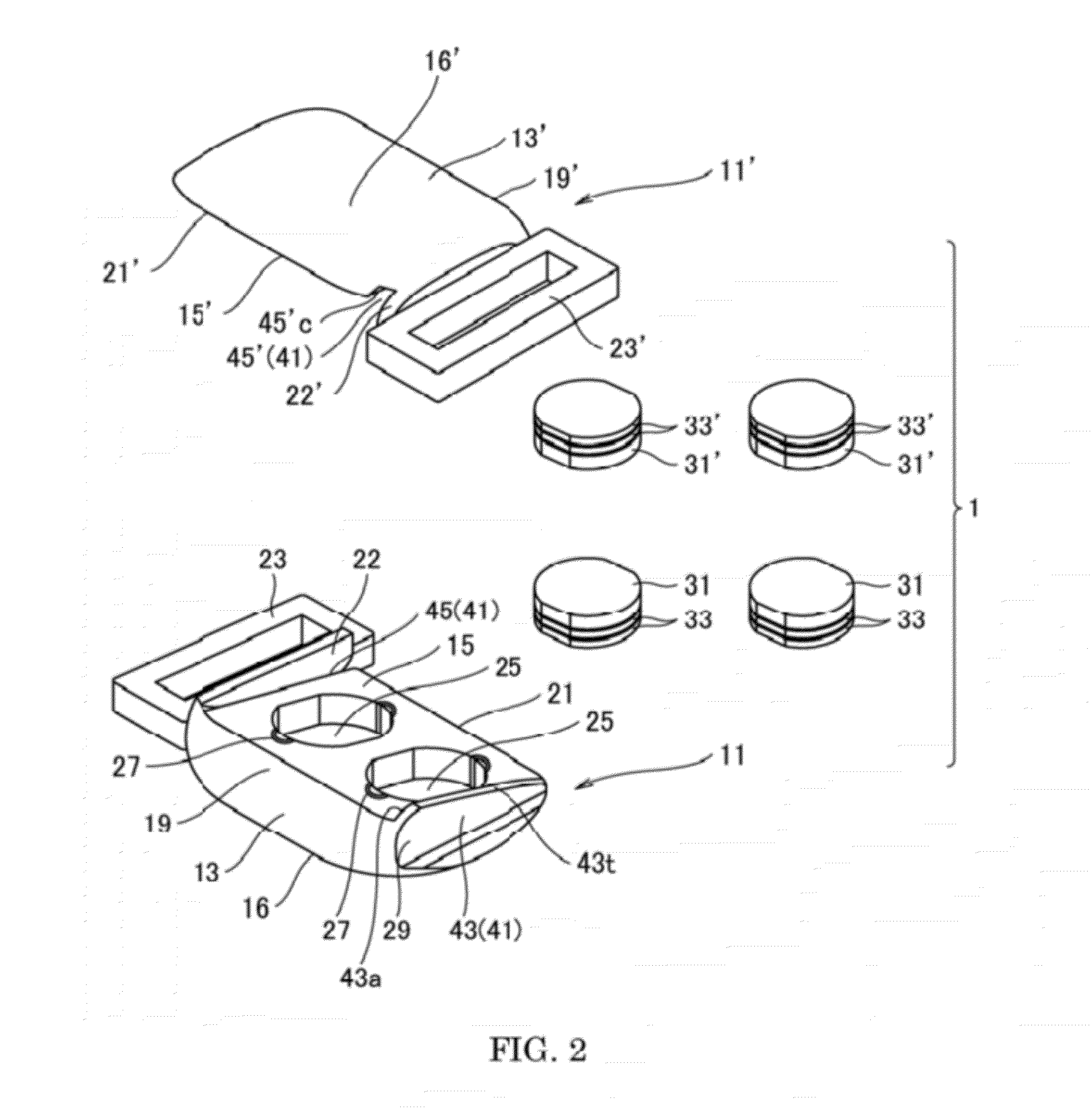
[0065]A first modified example of this embodiment is described with reference to FIGS. 9 to 13. In a coupling device 51 according to the first modified example, the connection is released or the release of the connection is assisted by the basically same principle as that of the coupling device 1 described above. Herein, a member different from that of the coupling device 1 is described and the same member name as that used in the coupling device 1 is used in the coupling device 51 for the common member and the description thereof is omitted as far as possible (the same applies to following modified examples).

[0066]That is to say, a coupling piece 52 according to the coupling device 51 is provided with a coupling piece main body 53 and an attaching piece 54 and the coupling piece main body 53 is provided with a joint surface 55 (refer to FIG. 11). A magnet piece 65 is embedded in an embedded hole 63 provided on the joint surface 55. A slide projected piece 67, whic...

second modified example

of this Embodiment

[0069]A second modified example of this embodiment is described with reference to FIGS. 14 to 18. A coupling device 51A according to the second modified example, is basically provided with the same structure as the structure of the coupling device 51, and difference therebetween is the slide guide structure of them. Therefore, the same reference sign is assigned to the member common to both and the description thereof is omitted. Hereinafter, the slide guide structure is described.

[0070]A slide guide structure 66A of the coupling device 51A is composed of a slide projected piece 67A (slide projected piece 67A′) and a slide groove 68A′ (slide groove 68A). The slide projected piece 67A is formed into a triangular shape in cross section, which inclines upward from one end in the pulling direction inward and vertically drops from an apex (refer to FIG. 18), so that the slide groove 68A′, which receives the same, also is formed into a triangular shape in cross section. ...

third modified example

of this Embodiment

[0072]A third modified example of this embodiment is described with reference to FIGS. 20 to 23. A coupling device 51B according to the third modified example is basically provided with the same structure as the structure of the coupling device 51A, and they are different from each other with respect to the slide guide structure and a fixing structure of the magnet of them. Therefore, the same reference sign is assigned to the member common to both and the description thereof is omitted. Hereinafter, the slide guide structure and the fixing structure are described.

[0073]Concave portions 67Bp and 68Bp being in egg-shapes, in a planar view are formed on a slide projected piece 67B and a slide groove 68B, which composes a slide guide structure 66B. As illustrated in FIG. 21, both of the concave portions 67Bp and 68Bp open upward and are laterally communicated with an embedded hole 67Bh. Two fixing claws 67Bk and 68Bk stand between the concave portions 67Bp and 68Bp an...


PUM

PropertyMeasurementUnit
magneticaaaaaaaaaa
pulling forceaaaaaaaaaa
magnetic forceaaaaaaaaaa

Abstract

A magnetic connecting device, which is easily separated without both hands but one that is not easily separated in a direction in which a pulling force is applied, is disclosed. Each of a pair of coupling pieces is respectively provided with each of a pair of coupling piece main bodies including joint surfaces capable of joining each other. At least one magnet piece is embedded in each of the joint surfaces such that the coupling piece main bodies attract to join each other. An attaching piece for attaching a string body is provided on each of the coupling pieces, and is provided with a slide guide structure formed on a side of the joint surface of each of the coupling piece main bodies for slidingly guiding the other in a predetermined direction with respect thereto.

Description

TECHNICAL FIELD[0001]The field relates to a magnetic coupling device attached to both ends of a string body such as an accessory such as a necklace and a bracelet, a waist belt, and other removable belts for coupling both the ends of the string body or releasing the connection.BACKGROUND[0002]The patent document 1 discloses a coupling device in which a tenon 113 (or dovetail) and a mortise 115 (or dovetail groove) are formed on one and the other of facing surfaces of magnets 111 and 121 in a direction perpendicular to a direction in which pulling force is applied illustrated in FIG. 24 (hereinafter, appropriately referred to as a “conventional coupling device”). There is an objective function that both the magnets attracting each other are not easily separated when pulling external force is applied by allowing the tenon to fit in the mortise.[0003]The Patent Document 1 referenced is Japanese Utility Model Application Laid-Open No. 60-79313, which makes reference to FIGS. 1 and 2.[00...

Claims


Application Information

Patent Timeline
Patent Type & Authority Applications(United States)
IPC IPC(8): H01F1/00
CPCH01F7/04H01F7/0263A44B11/258A44B11/2596A44C5/2085A44D2203/00
Inventor NINOMIYA, TOMOYASU
Owner SEBERU PICO
Why Eureka
Try Eureka