Color management and calibration using a scanner or camera

a color management and camera technology, applied in the field of color management and calibration using a scanner or camera, can solve the problems of inability to perform important uniformity measurements, wasting hundreds of pages each time such color management functions are updated, and increasing costs

Inactive Publication Date: 2012-02-23
XEROX CORP
View PDF4 Cites 33 Cited by
  • Summary
  • Abstract
  • Description
  • Claims
  • Application Information

AI Technical Summary

Benefits of technology

[0010]According to another aspect of the present disclosure, a system for color calibration and profiling of an output device is provided. The system includes a print engine, a first sensor, a second sensor, and a processor. The print engine is configured to print a test pattern comprising a plurality of patches thereon. The first sensor is configured to measure a color patch in the test pattern to obtain first image data. The first image data provides a measured color representation of the color patch in a device dependent color space. The second sensor is configured to measure the color patch in the test pattern to obtain second image data. The second image data provides a measured color representation of the color patch in a device independent color space. The processor is configured to: a) transform the first image data to a first estimated image data; b) determine a difference between the second image data and the first estimated image data to obtain a correction factor; and c) calculate, for each patch in the test pattern, a corrected image data by applying the correction factor to a subsequent estimated image data from the first sensor. The first estimated image data provides an estimated color representation of the first image data in the device independent color space. The correction factor is used for correcting inaccuracies introduced when the subsequent image data is transformed into the subsequent estimated image data.

Problems solved by technology

While the ILS contributes significantly to better performance (i.e., productivity and customer convenience), the ILS measures the color (e.g., in a device independent color space, such as L*a*b*) at only one location in a cross-process direction of the image printing device, unless more than one ILS is used, which is more expensive.
Since hundreds, or even thousands, of color patches are needed for color management functions, such as generating a destination profile for the printer or populating a spot color table, hundreds of pages are wasted each time such color management functions are updated.
Moreover, the ILS cannot perform important uniformity measurements, such as IBOB (inboard-outboard) color variation.
It is possible to profile a scanner, such as a FWA scan bar, to generate color (L*a*b*) data from the RGB signals, but with available technology this can only be done approximately.
The accuracy attainable is quite inadequate for some color management functions, such as generating a destination profile for the printer or populating a spot color table.

Method used


Image

  • Color management and calibration using a scanner or camera
  • Color management and calibration using a scanner or camera
  • Color management and calibration using a scanner or camera

Examples


Embodiment Construction

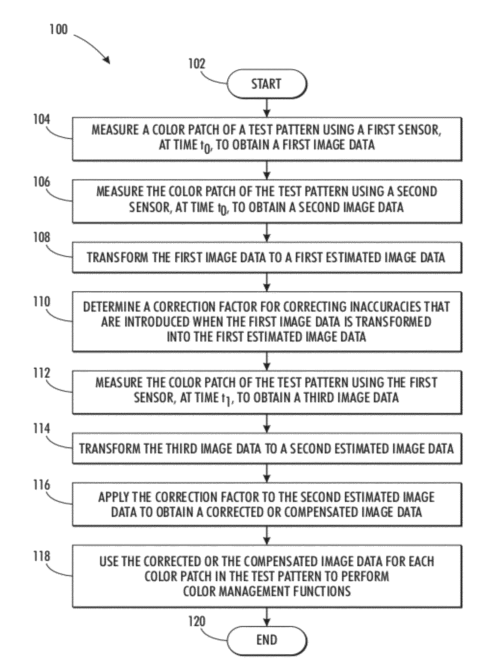
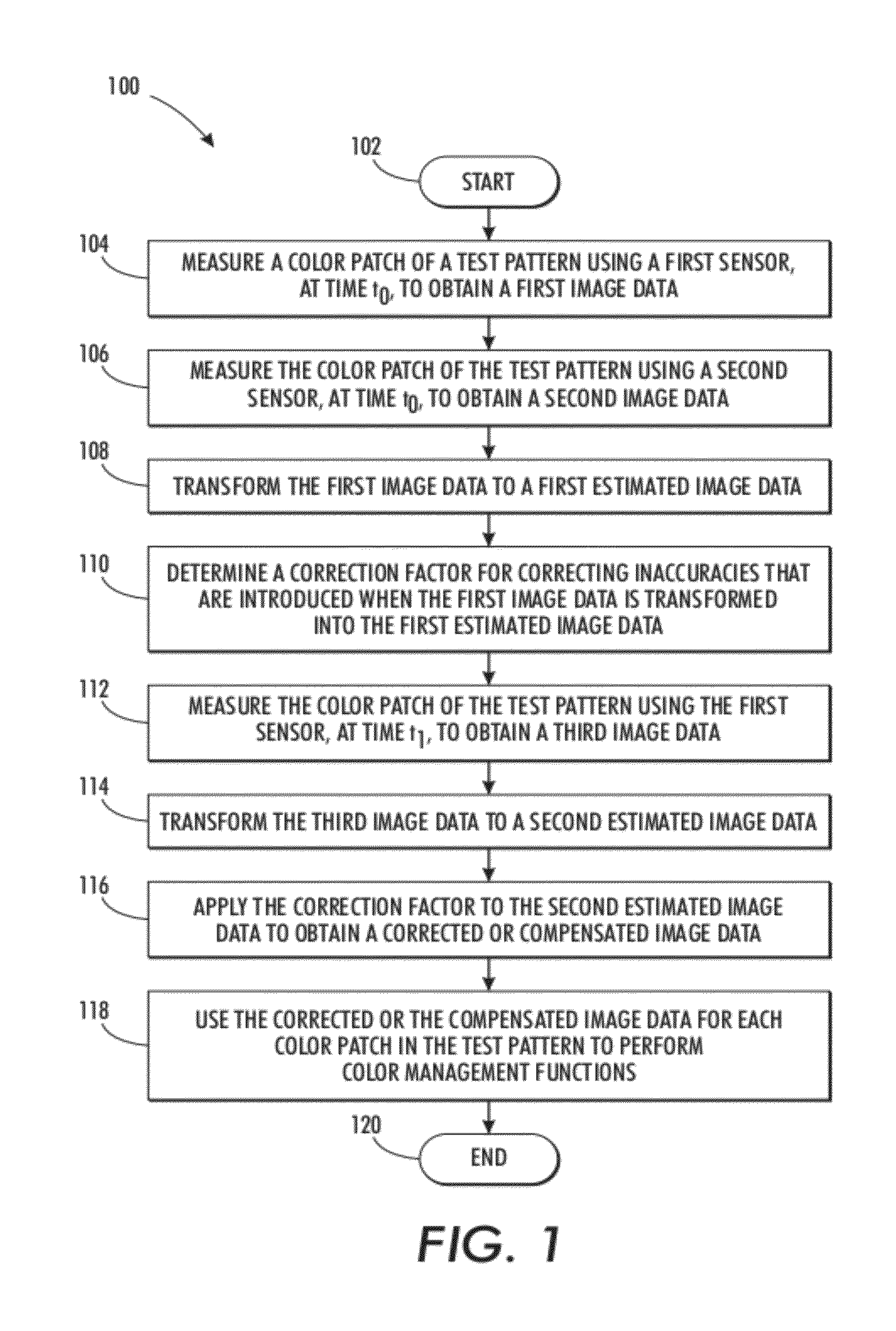
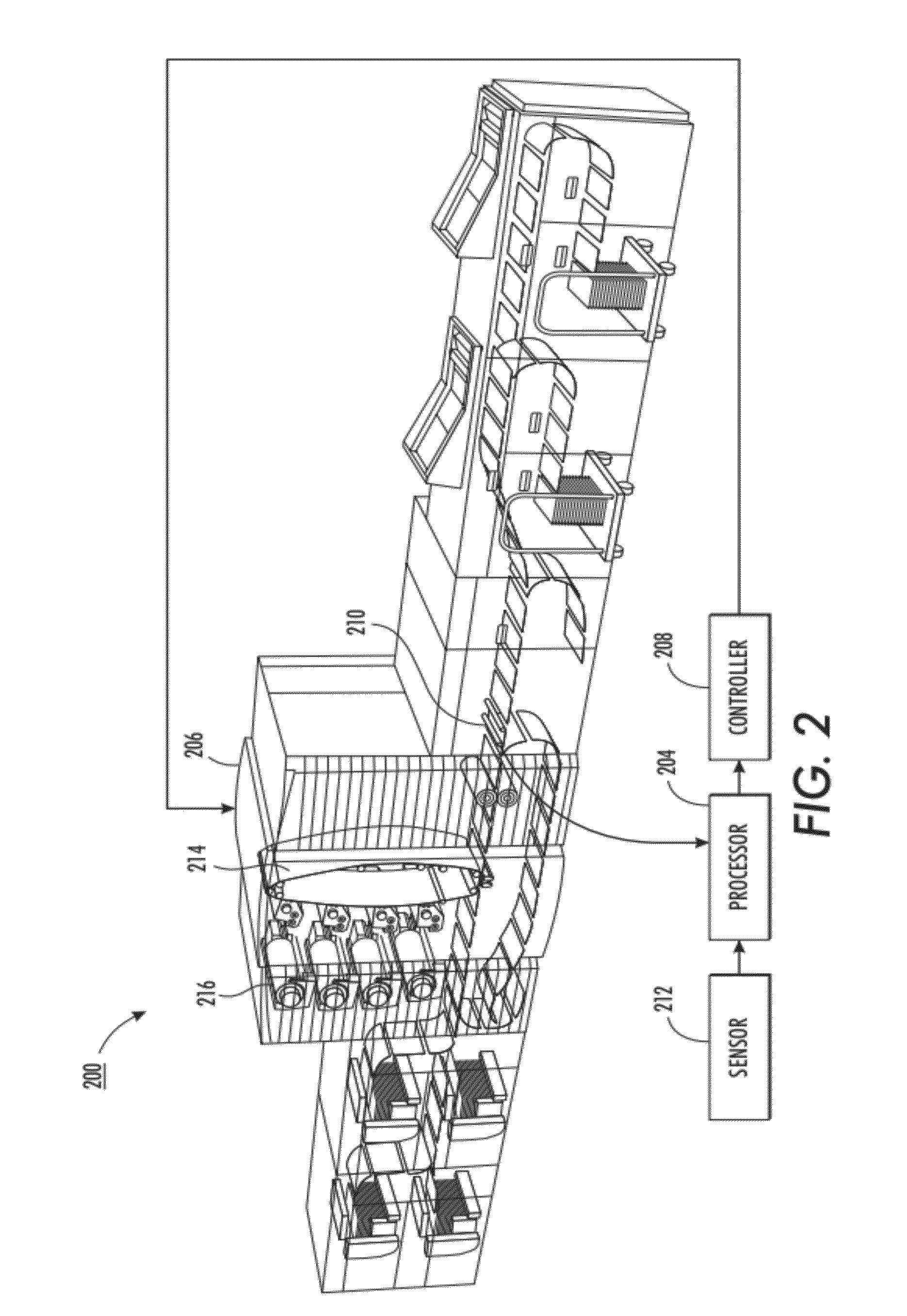
[0018]An image printing system 200, as shown in FIG. 2, generally has two important directions: a process (or a slow scan) direction and a cross-process (or a fast scan) direction. The direction in which an image bearing surface 214, as shown in FIG. 2, moves is referred to as the process (or the slow scan) direction, and the direction perpendicular to the process (or the slow scan) direction is referred to as the cross-process (or the fast scan) direction.

[0019]The generation of color documents includes an image output step, where the image is printed by a color printer or other image output device. Most color output devices either use cyan, magenta and yellow signals in a CMY color space or in a CMYK with an additional color signal for black. The color signals used for image output devices are also usually device-dependent. Instead of transferring color signals in the RGB space from a scanner directly to color signals in the CMYK space to a color printer, a device-independent colo...


PUM


Abstract

A computer-implemented method for color calibration and profiling of an output device includes measuring a color patch in a test pattern, which comprises a plurality of color patches, to obtain first image data; measuring the color patch in the test pattern to obtain second image data; transforming the first image data to a first estimated image data; determining a difference between the second image data and the first estimated image data to obtain a correction factor; and calculating, for each patch in the test pattern, a corrected image data by applying the correction factor to a subsequent estimated image data from the first sensor. The correction factor is used for correcting inaccuracies introduced when the first image data is transformed into the first estimated image data. The first image data and the second image data provide a measured color representation of the color patch in a device dependent color space and a device independent color space, respectively.

Description

BACKGROUND[0001]1. Field[0002]The present disclosure relates to a method and a system for color calibration and color profiling of an image output device, such as an image printing device.[0003]2. Description of Related Art[0004]Some image printing devices have inline color measurement equipment, such as an inline spectrophotometer (ILS), to perform color management functions (e.g., color profiling and color calibration). On the other hand, some image printing devices have a full width array (FWA) or partial width array (PWA) scan bar to evaluate and / or correct image quality variation in the cross-process direction of the image printing device.[0005]The ILS is used for color management. While the ILS contributes significantly to better performance (i.e., productivity and customer convenience), the ILS measures the color (e.g., in a device independent color space, such as L*a*b*) at only one location in a cross-process direction of the image printing device, unless more than one ILS ...

Claims


Application Information

Patent Timeline
Patent Type & Authority Applications(United States)
IPC IPC(8): G06K15/00H04N1/46G01J3/42G06K9/00
CPCH04N1/6033G01J3/462
Inventor DALAL, EDUL N.WU, WENCHENG
Owner XEROX CORP
Why Eureka
Try Eureka