Electrical power tools

Inactive Publication Date: 2012-02-23
MAKITA CORP
View PDF16 Cites 14 Cited by
  • Summary
  • Abstract
  • Description
  • Claims
  • Application Information

AI Technical Summary

Benefits of technology

[0009]According to this aspect, the tool main body can be removed from the base while the male elevating member is left in the base. Therefore, it is not necessary to disengage the female elevating member from the male elevating member in order

Problems solved by technology

However, in order to remove the tool main body from the ba

Method used


Image

  • Electrical power tools
  • Electrical power tools
  • Electrical power tools

Examples


Example

[0021]A representative embodiment of the present invention will now be described in detail with reference to FIGS. 1 to 8.

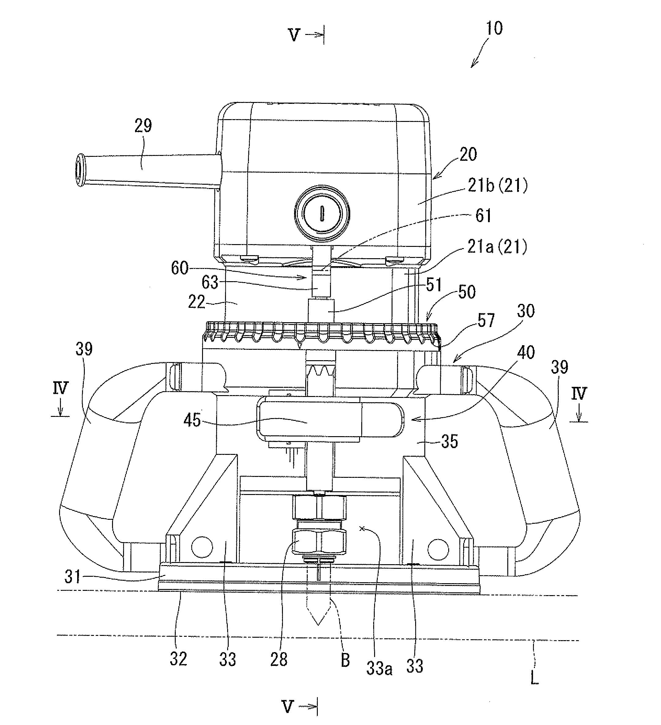
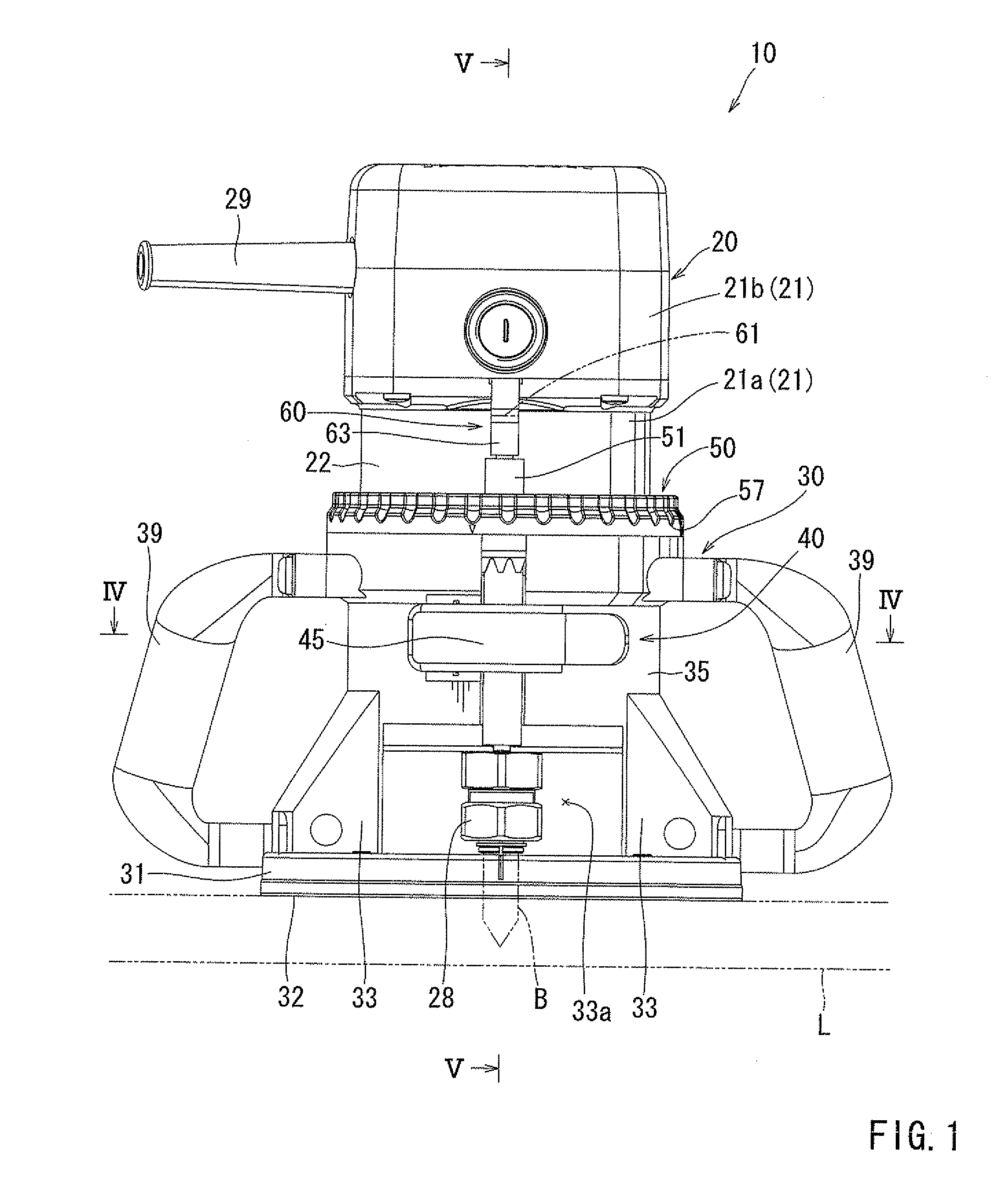
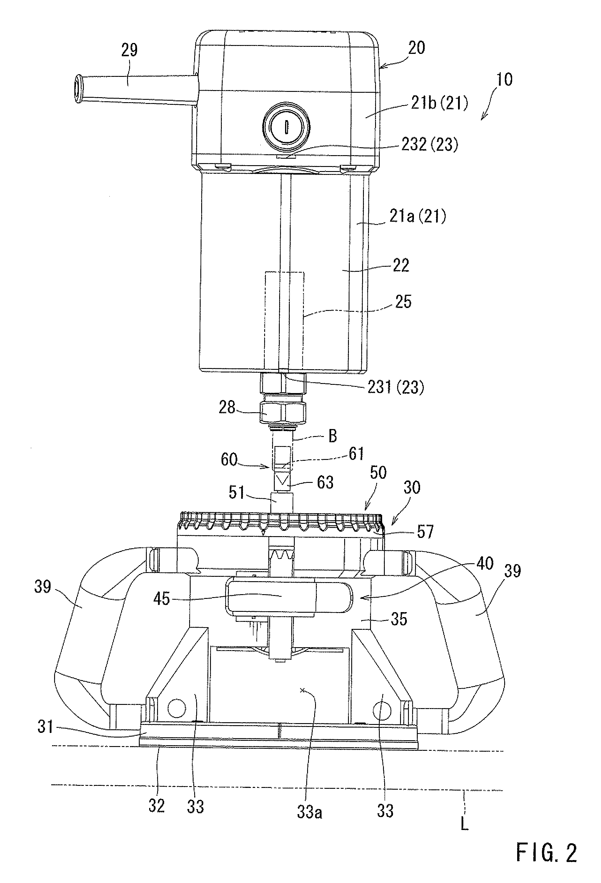
[0022]In this embodiment, a router or trimmer is exemplified as an electrical power tool 10. As will be recognized, the router (trimmer) is a device that is constructed to trim or groove a work-piece L such as a woody material. Further, an up and down direction in the description corresponds to a vertical direction of FIGS. 1, 2 and 5-8.

[0023]As shown in FIGS. 1 and 2, the electrical power tool 10 may include a tool main body 20, and a base 30 that is capable of supporting the tool main body 20. The electrical power tool 10 thus constructed is disposed on the work-piece L while the base 30 contacts the work-piece L, so as to process (trim or groove) the work-piece L. Further, the electrical power tool 10 may include an elevating (raising and lowering) mechanism 50 that is capable of raising and lowering the tool main body 20 to adjust a (relative) position of the...


PUM


Abstract

An electrical power tool may include a base capable of contacting the work-piece, a tool main body detachably attached to the base, and an elevating mechanism that is capable of changing a relative position of the tool main body to the base. The elevating mechanism includes a male elevating member that is releasably integrated with the tool main body, a female elevating member that is attached to the base and is capable of relatively raising and lowering the male elevating member, and an integrating mechanism that is capable of releasably integrating the male elevating member with the tool main body. The tool main body is capable of being removed from the base while the male elevating member is left in the base when the male elevating member is released from the tool main body by operating the integrating mechanism.

Description

BACKGROUND OF THE INVENTION[0001]1. Field of the Invention[0002]The present invention relates to electrical power tools. More particularly, the present invention relates to electrical power tools that are constructed to trim or groove work-pieces such as woody materials.[0003]2. Description of Related Art[0004]An electrical power tool that is constructed to trim or groove a work-piece such as a woody material is generally known. Such an electrical power tool is called as a router or trimmer. The electrical power tool includes a tool main body having a spindle, and a base that is capable of supporting the tool main body and contacting the work-piece. In the electrical power tool, it is necessary to determine a position of a tool bit relative to the work-piece. Generally, in order to determine the position of the tool bit relative to the work-piece, a relative position of the tool main body to the base is determined, so that a relative position of the tool main body to the work-piece ...

Claims


Application Information

Patent Timeline
IPC IPC(8): B27C5/10B23C1/20
CPCB27C5/10Y10T409/306608Y10T409/307952
Inventor SHIBATA, YOSHINORIKIMURA, TAKUJI
Owner MAKITA CORP
Why Eureka
Try Eureka