Upgoing drainholes for reducing liquid-loading in gas wells

Active Publication Date: 2012-03-01
BAKER HUGHES INC
View PDF1 Cites 37 Cited by
  • Summary
  • Abstract
  • Description
  • Claims
  • Application Information

AI Technical Summary

Benefits of technology

[0008]It should be understood that examples of the more important features of the disclosure have been summarized rather broadly in order that detailed description thereof that follows may be better understood, and in order that the contributions to the art may be appreciated. There are, of course, additional features of the disclosure that will be described hereinafter and which will form the subject of the claims appended hereto.

Problems solved by technology

In contrast to conventional gas formation that flow with relatively ease from drilled wells, the recovery of tight gas reservoirs can be uneconomical in many situations.

Method used


Image

  • Upgoing drainholes for reducing liquid-loading in gas wells
  • Upgoing drainholes for reducing liquid-loading in gas wells
  • Upgoing drainholes for reducing liquid-loading in gas wells

Examples


Embodiment Construction

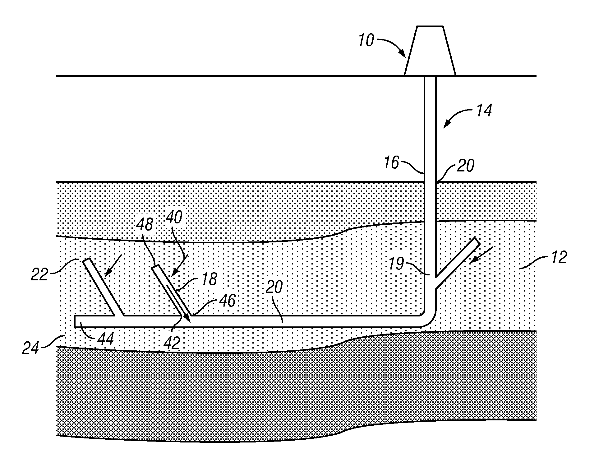
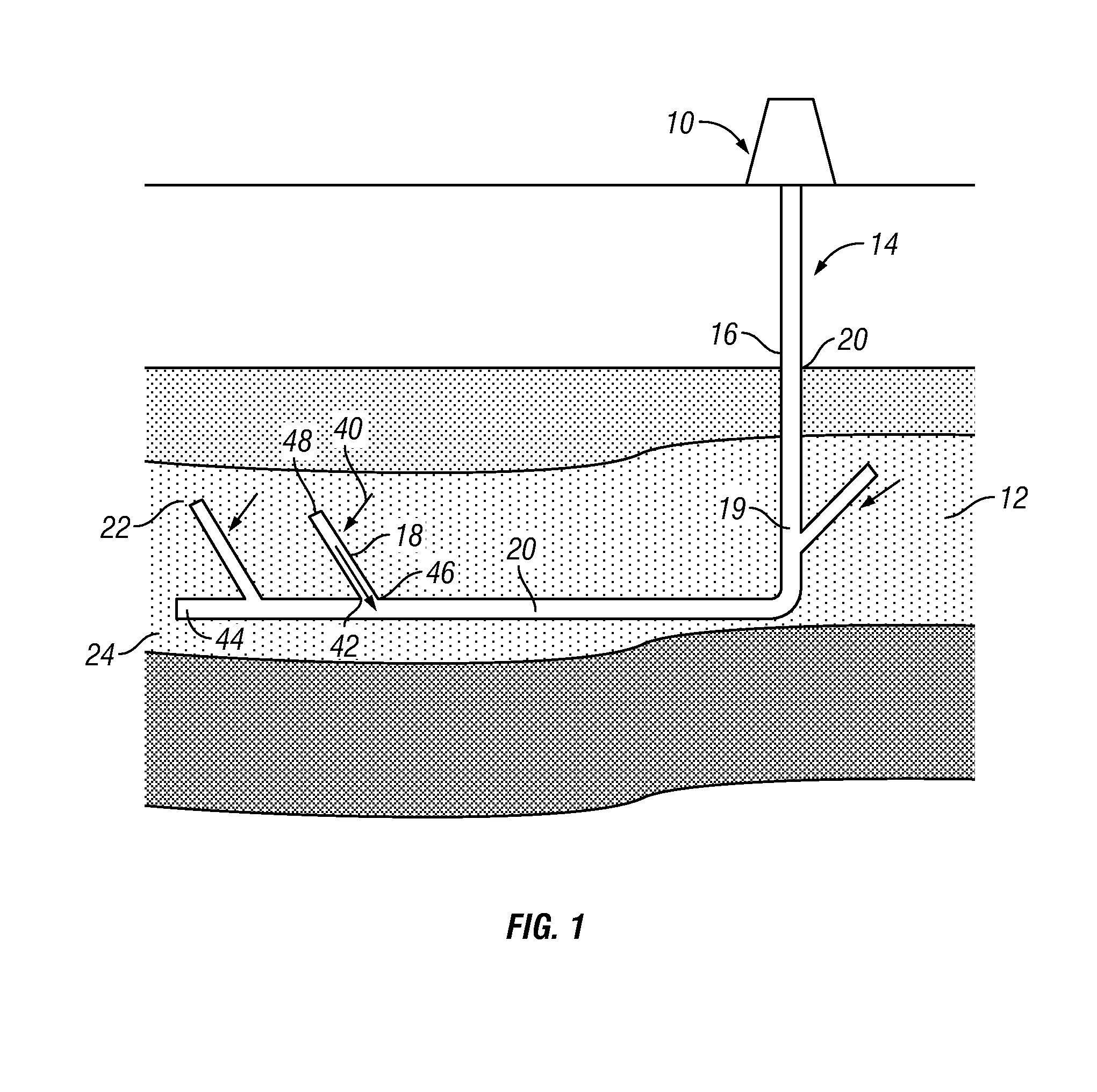
[0015]Aspects of the present disclosure may be utilized to recover gas, e.g., natural gas, from subterranean formations. The present disclosure is susceptible to embodiments of different forms. That is, certain embodiments of the present disclosure may be utilized in other applications. The specific embodiments of the present disclosure described herein, therefore, are presented with the understanding that the present disclosure is to be considered an exemplification of the principles of the disclosure, and is not intended to limit the disclosure to that illustrated and described herein.

[0016]Liquid-loading may be a problem for gas wells that produce a liquid, such as water. The produced liquid may be mobile water in a reservoir, aquifer water, coning water from a water zone, condensate gas, and / or human injected water. As used herein, the term “water” includes water-based liquids, such as brine. When the flow rate of a produced gas is sufficiently high, the produced liquid form dro...


PUM


Abstract

Gas from a tight gas formation may be produced using a drain hole having a juncture to a main wellbore and a terminal end at a depth higher than the juncture. The terminal end may be positioned in the tight gas formation.

Description

CROSS-REFERENCE TO RELATED APPLICATIONS[0001]This application claims priority from U.S. Provisional Application Serial No. 61 / 377695 filed Aug. 27, 2010, the disclosure of which is incorporated herein hereby in its entirety.BACKGROUND OF THE DISCLOSURE[0002]1. Field of the Disclosure[0003]The disclosure relates to enhancing production of hydrocarbons from tight gas reservoirs.[0004]2. Description of the Prior Art[0005]Tight gas refers to “natural gas” produced from reservoirs having relatively low permeability. Tight gas can be trapped in sandstone or carbonate or shale formations, of which the low permeability and porosity impede the gas flow. In contrast to conventional gas formation that flow with relatively ease from drilled wells, the recovery of tight gas reservoirs can be uneconomical in many situations. The present disclosure is directed to well construction methods and systems that allow tight gas formations to be more economically produced.SUMMARY OF THE DISCLOSURE[0006]In...

Claims


Application Information

Patent Timeline
IPC IPC(8): E21B43/00E03B3/11
CPCE21B43/305E21B43/121
Inventor LI, BAOYANGRIMMER, HARALDKRUEGER, VOLKER
Owner BAKER HUGHES INC
Why Eureka
Try Eureka