Current isolation contactor

Inactive Publication Date: 2012-03-01
INT BATTERY
View PDF3 Cites 7 Cited by
  • Summary
  • Abstract
  • Description
  • Claims
  • Application Information

AI Technical Summary

Problems solved by technology

These critical events can lead to safety issues and other issues that can harm the battery and / or the device being powered.

Method used


Image

  • Current isolation contactor
  • Current isolation contactor
  • Current isolation contactor

Examples


Embodiment Construction

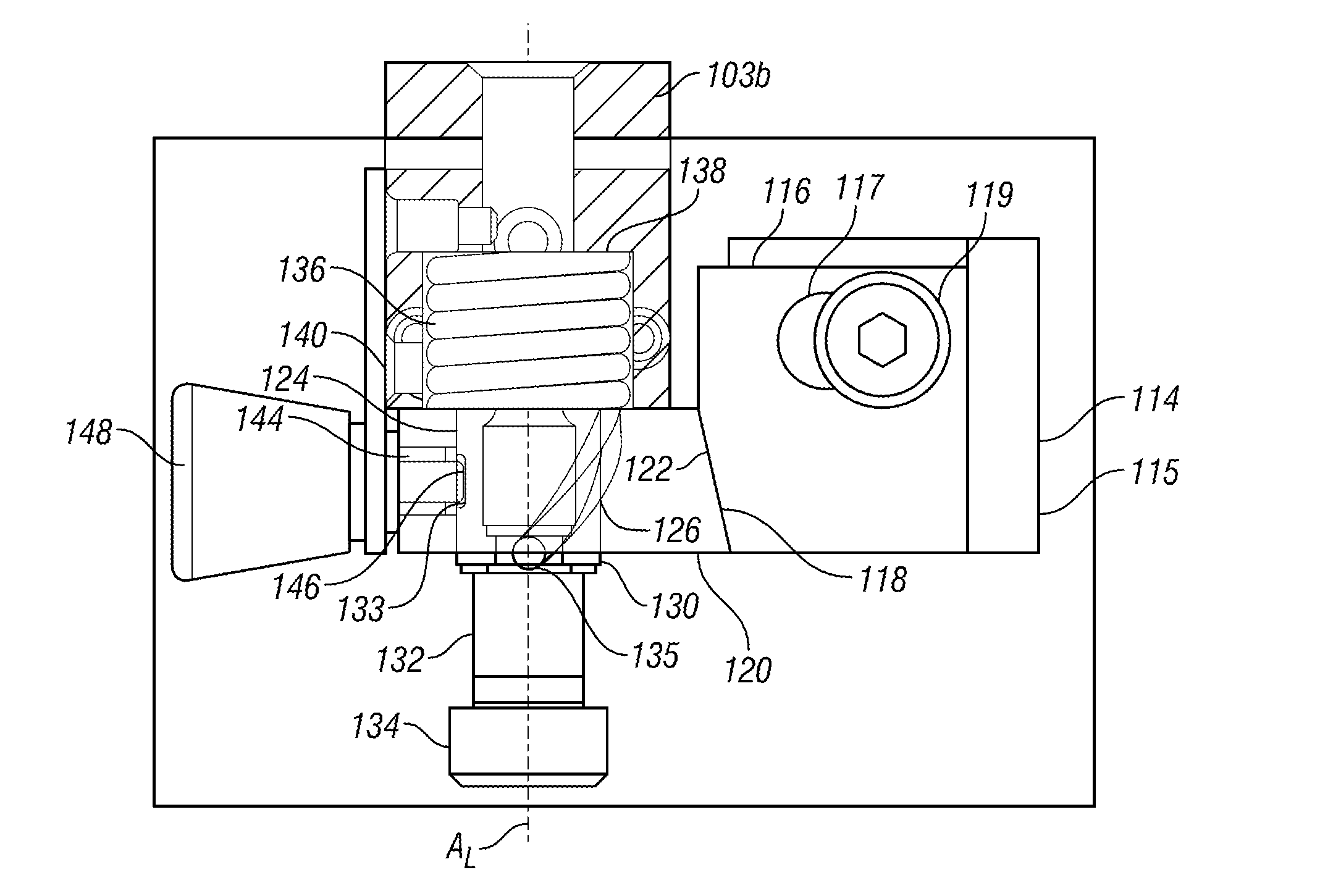
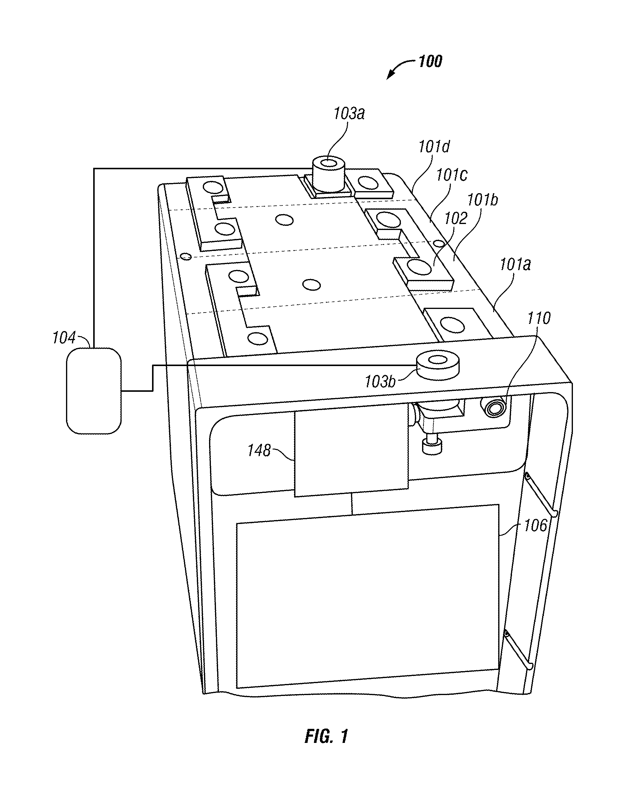
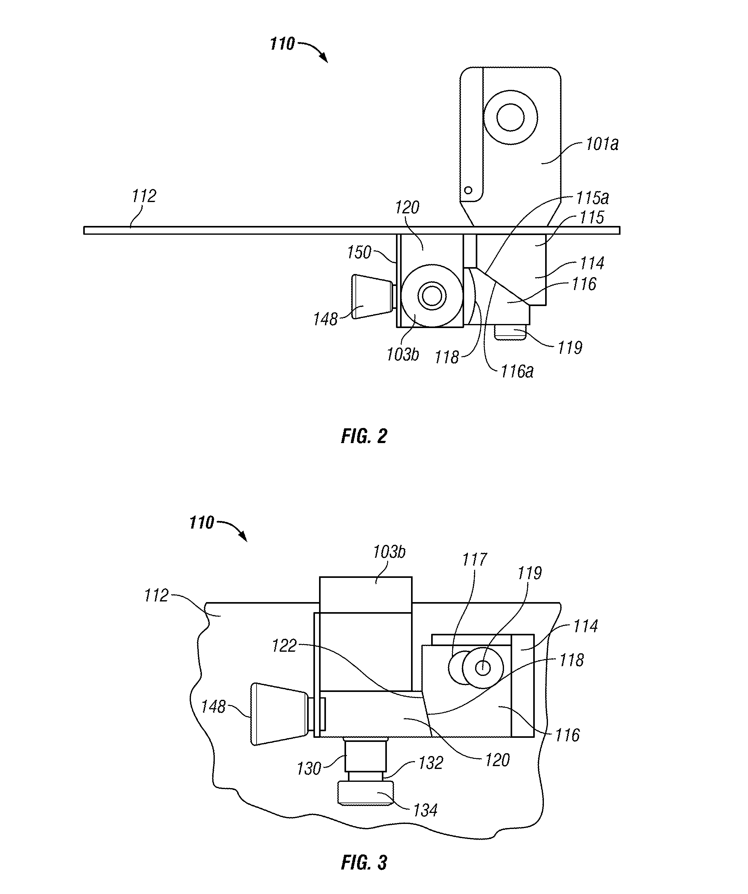
[0020]In describing the embodiments of the invention illustrated in the drawings, specific terminology will be used for the sake of clarity. However, the invention is not intended to be limited to the specific terms so selected, it being understood that each specific term includes all technical equivalents operating in similar manner to accomplish similar purpose. As used herein, devices are “electrically engaged” with each other or are in “electrical engagement” with each other when a path is provided for a transfer of electrons between the devices. Similarly, devices are “electrically disengaged” from each other or are in “electrical disengagement” from each other when a path is not provided for a transfer of electrons between the devices. Also, a “battery” may be comprised of a single cell or multiple cells. It is understood that the drawings are not drawn to scale.

[0021]The following describes particular examples of embodiments of the present invention. It should be understood, ...


PUM


Abstract

A current isolation contactor includes a first contact, a second contact movable between an engaged position with the first contact and a disengaged position away from the first contact, and a cam being movable between a biased position wherein the second contact is in the engaged position with the first contact and an unbiased position wherein the second contact is able to move to the disengaged position away from the first contact. A retaining pin retains the cam in the biased position. A drive system is operatively associated with retaining pin to move the retaining pin, allowing the cam to rotate to the unbiased position such that the second contact is moved to the disengaged position.

Description

FIELD OF INVENTION[0001]The present invention relates to an electrical contactor for an electrical system that automatically breaks contact and electrically separates a power supply from a powered device when a critical event occurs.BACKGROUND OF THE INVENTION[0002]For a wide range of applications of lithium ion batteries, a mechanism for isolating large current loads is useful to protect both the batteries and the powered device resulting from the occurrence of a critical event. Exemplary critical events may include a reversal of polarity when the terminals of the battery are connected backwards, a short circuit resulting from positive and negative terminals being linked together by a conductor, an overcharge condition that results from continued battery charging after a battery cell is fully charged, a forced discharge condition that results from one of the battery cells reaching a minimum specified cell voltage, or an over temperature condition when any cell in the battery exceed...

Claims


Application Information

Patent Timeline
IPC IPC(8): H01H5/00
CPCH01H1/34H01H1/50H01H39/00
Inventor ALMGREN, AKEREIS, ANTONIOPRITSKER, ILYAEARLE, JR., GREGORY
Owner INT BATTERY
Why Eureka
Try Eureka