Method and apparatus for osteosynthesis

a technology of osteosynthesis and bone plate, applied in the field of orthopaedic bone plate, can solve the problems of increasing non-union, malunion, avascular necrosis, etc., and reducing tends to leave a void

Inactive Publication Date: 2012-03-01
KIRITSIS PAUL
View PDF3 Cites 16 Cited by
  • Summary
  • Abstract
  • Description
  • Claims
  • Application Information

AI Technical Summary

Problems solved by technology

However, anatomic reduction tends to leave a void adjacent to a realigned or repositioned fragment.
Voids th...

Method used


Image

  • Method and apparatus for osteosynthesis
  • Method and apparatus for osteosynthesis
  • Method and apparatus for osteosynthesis

Examples


Embodiment Construction

[0022]The following description is merely exemplary in nature and is not intended to limit the present disclosure, application, or uses. It should be understood that throughout the drawings, corresponding reference numerals indicate like or corresponding parts and features.

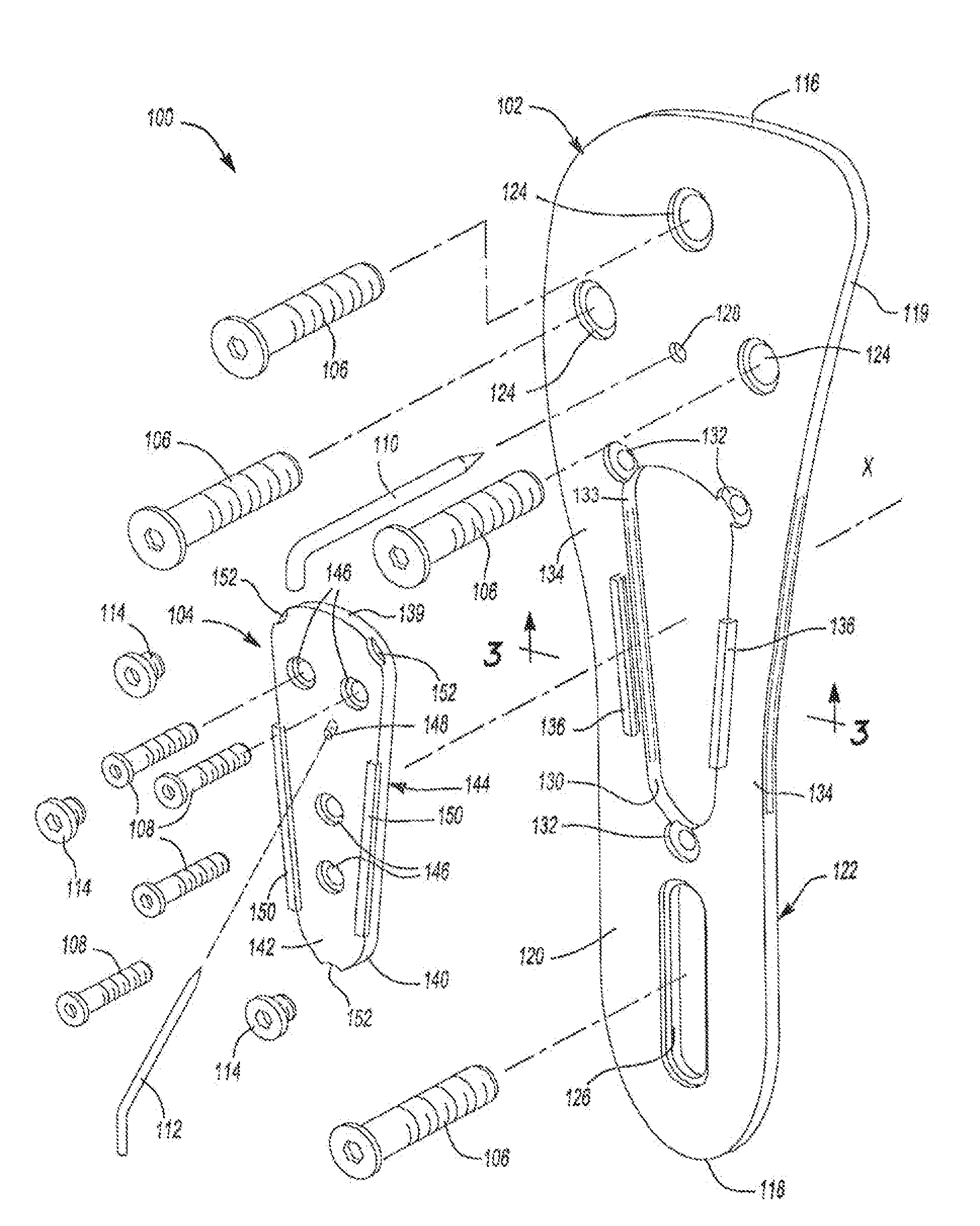
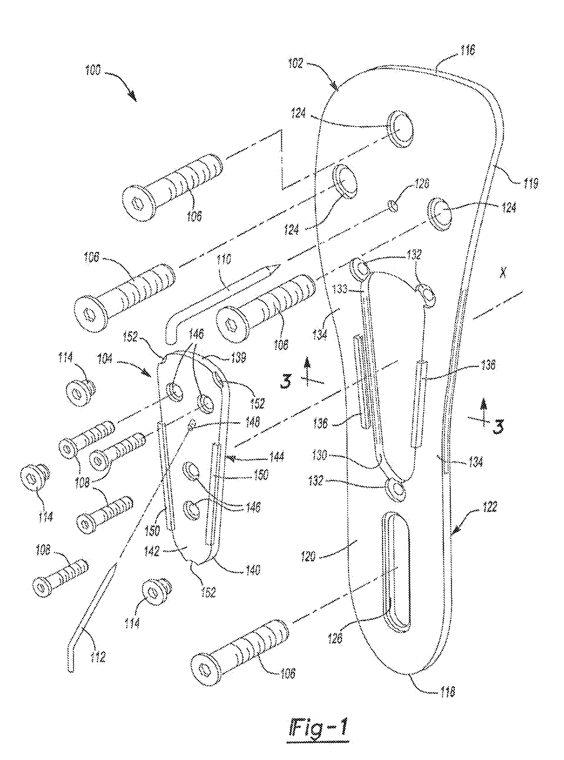
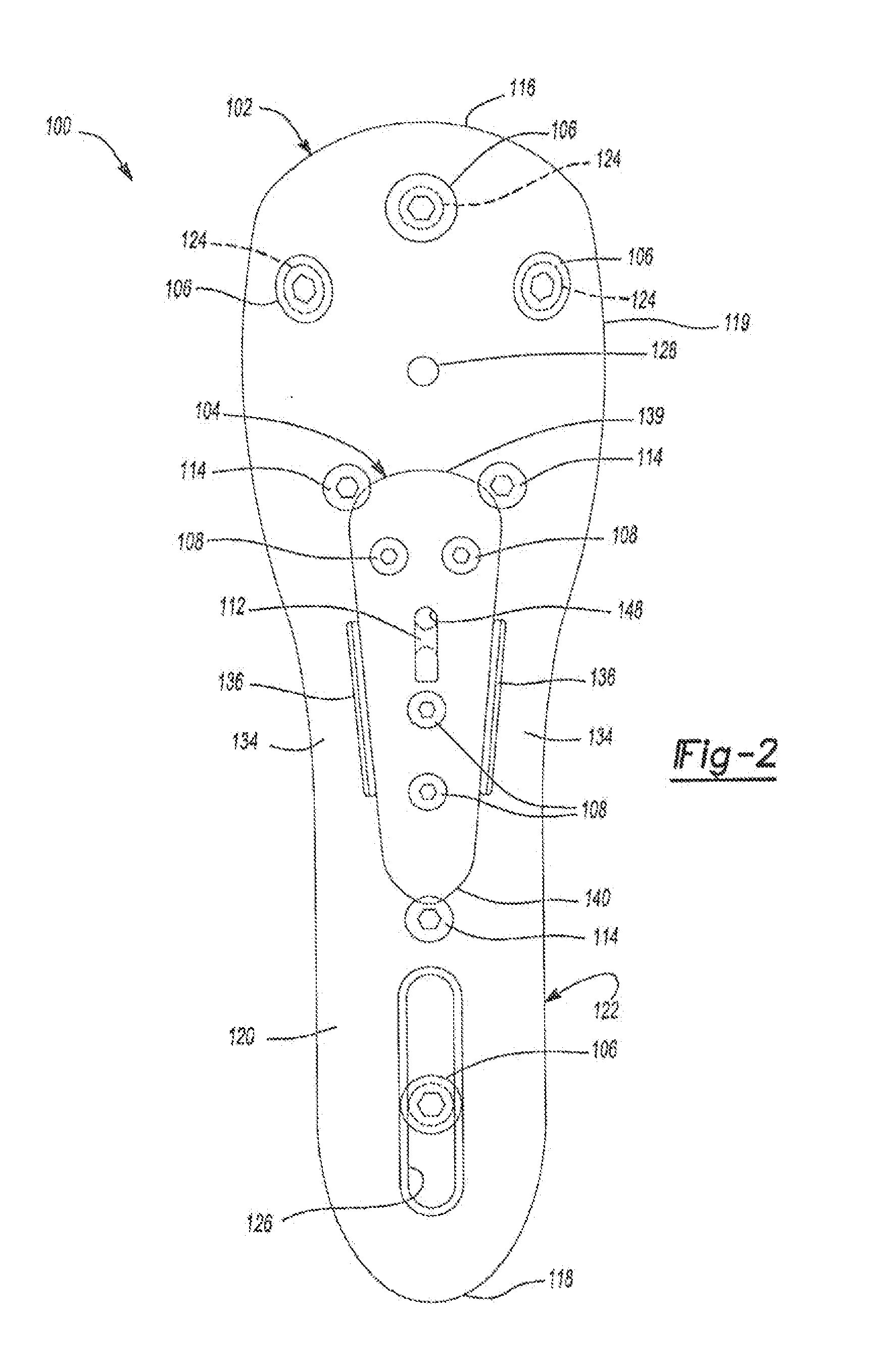
[0023]Referring to FIGS. 1 through 3, a bone plate assembly 100 is illustrated according to various exemplary embodiments of the present disclosure. The bone plate assembly 100 can include a first or main plate 102, a second or cover plate 104, main plate bone screws 106, cover plate bone screws 108, main plate Kirchner wire (K wire) 110, cover plate K wire 112, and set screws 114. The main and cover plates 102, 104 can be shaped to substantially or generally conform to or mate with a plate-engaging surface of a bone, such as but not limited to a lateral surface of a proximal humerus, the distal radius, proximal femur, distal femur, proximal and distal tibia, and calcaneus.

[0024]The bone screws 106, 108 can be ins...


PUM


Abstract

A bone plate assembly including a first plate, a coupler, a second plate, and a guide; the first plate defining a window and having a first major surface adapted to conform to a native bone structure. The coupler such as a beveled edge and/or slide mechanism can be formed on a second major surface of the first plate opposite the first major surface. The second plate can be adapted to engage the coupler, to cover the window, and to conform to the native bone structure. The second plate can include through holes adapted to receive bone screws. The guide can be adapted to engage the coupler and to guide at least one of a cutting tool and/or a dilation tool. The native bone structure is distal radius, proximal femur, distal femur, proximal tibia, distal tibia or calcaneus.

Description

CROSS-REFERENCE TO RELATED APPLICATION[0001]This application claims the benefit of Continuation-In-Part application Ser. No. 12 / 871,423, filed Aug. 30, 2010, which is hereby incorporated by reference in its entirety.FIELD OF THE INVENTION[0002]The following relates to orthopaedic bone plates, and more specifically, relates to plates for reducing and fixing complex bone fractures.BACKGROUND OF THE INVENTION[0003]The statements in this section merely provide background information related to the present disclosure and does not constitute prior art.[0004]Orthopaedic bone plates have been developed for osteosynthesis, or the reduction and fixation, of complex bone fractures. Typically, anatomic reduction is performed on fragments of a bone before fixing the fragments to the bone via plates and fasteners. The fragments arc then fixed to the bone while the bone heals to improve anatomic alignment of the fragments and minimize anatomic congruities and dysfunction. However, anatomic reducti...

Claims


Application Information

Patent Timeline
IPC IPC(8): A61B17/80
CPCA61B17/17A61B17/1728A61B17/175A61B2017/1778A61B17/80A61B17/8805A61B17/885A61B17/1764A61B17/1778
Inventor KIRITSIS, PAUL
Owner KIRITSIS PAUL
Why Eureka
Try Eureka