Unlock instant, AI-driven research and patent intelligence for your innovation.
Gastrointestinal device
Inactive Publication Date: 2012-03-01
UNIV LIBRE DE BRUXELIES
View PDF4 Cites 28 Cited by
Summary
Abstract
Description
Claims
Application Information
AI Technical Summary
This helps you quickly interpret patents by identifying the three key elements:
Problems solved by technology
Method used
Benefits of technology
Benefits of technology
[0029]Preferably, the volume of the (tissue) abutting member is higher than (about)
Problems solved by technology
This manner of attaching such type of device does not allow a long-term anchoring.
This type of capsule, due to its shape, cannot be implanted in sphincters such as the pyloric sphincter.
Method used
Image
Click on the blue label to locate the original text in one second.
Reading with bidirectional positioning of images and text.
Examples
example 1
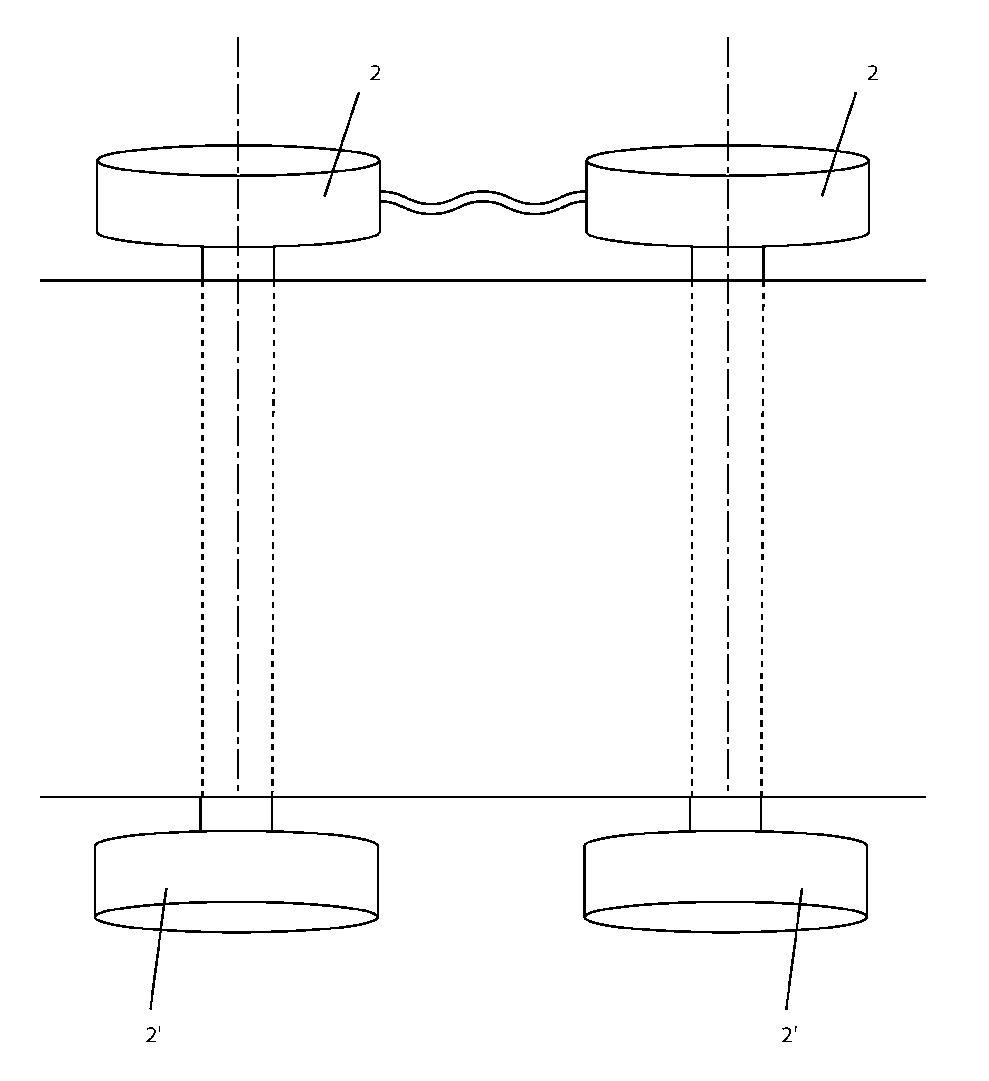
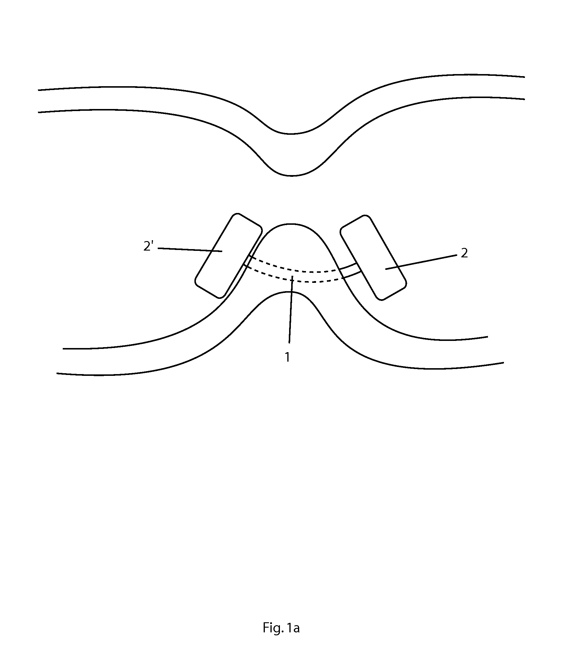
[0192]The implant presented in FIG. 1 comprises two tissue abutting members (2 and 2′) having a plug shape and respectively connected to one elongated body (1) end.
[0193]For example, the tissue abutting members (2 and 2′) that are fixed to the ends have a section as the ones displayed in FIG. 7.
[0194]As depicted at FIGS. 2a and 2b, these (tissue) abutting members comprise a circuit (5) and a power supply (11) respectively.
[0195]Furthermore, the (tissue) abutting members as depicted in FIGS. 2a and 2b further comprise isolation material (6).
[0196]Before being anchored in the tissue(s), at least one (tissue) abutting member is not fixed (or is even not attached) at one end of the elongated body.
[0197]The perforating means of the elongated body are sharp elements located at the tip of the elongated body ends that enable to perforate the tissue in which the implant has to be anchored.
[0198]Preferably—as depicted in FIG. 4a—the connection means of the elongated body (1) and the (tissue) ...
example 2
[0208]The implant presented in FIGS. 7, 8, and 9 comprises one plug shape (tissue) abutting member (2) and one (tissue) abutting member (2′) that has a deploying (or deployable) part (30), both elements being connected to separate elongated body ends.
[0209]In this case, the (tissue) abutting member comprising the deploying part (30) is connected to the distal end of the elongated body prior to the perforation of the tissue(s) by the implant.
[0210]Preferably, said deploying part (30) has at least a retracted configuration—as depicted in FIG. 7—and a deployed configuration—as depicted in FIG. 8—, both configurations being preferably two 3-dimensional configurations.
[0211]Preferably, the deploying part comprises at least one member that is arranged to deploy, thereby increasing the maximum orthogonal section of the implant, as depicted in FIG. 9c.
[0212]Alternatively, the deploying part comprises at least two members that are arranged to deploy, thereby increasing the maximum orthogona...
example 3
[0220]The implant presented in FIGS. 10 and 11 comprises a pair of implants in accordance with the present invention that are connected by a physical connection between two adjacent abutting members respectively belonging to each implant.
PUM
Abstract
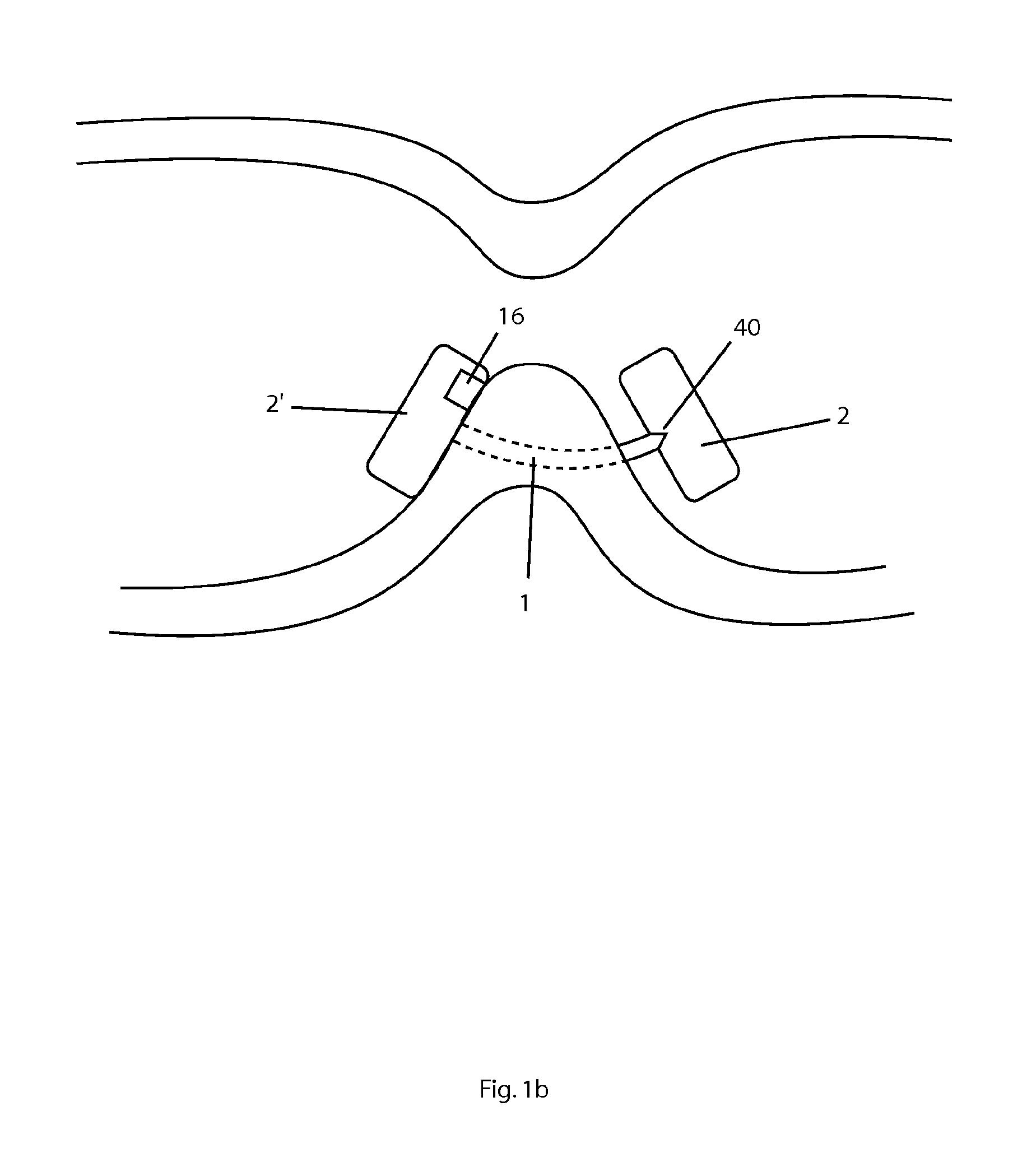
A gastrointestinal device to be implanted into an animal or human tissue includes an elongated body (1) having a first end and a second end, and at least a first abutting member (2) at the first end of the elongated body (1). The device also includes a second abutting member (2′) at the second end of the elongated body (1), which is flexible. The device further includes at least one electrode (16) and a power supply (11) for supplying current to the electrode (16).
Description
FIELD OF THE INVENTION[0001]The present invention relates to a surgical device to be implanted. In particular, the present invention relates to a gastrointestinal implant that enables to reduce food uptake, and thereby controlling overweight, and accordingly which will be placed in the gastrointestinal tract.STATE OF THE ART[0002]Document U.S.-2006 / 0265021-A1 describes a gastrointestinal implant in the form of a rigid capsule comprising a cavity wherein the stomach wall is sucked. The sucked tissue is penetrated with a pin holding the capsule in place. The pin forms the electrode. This manner of attaching such type of device does not allow a long-term anchoring. It is moreover used for pHmetric capsules such as the one disclosed in U.S. Pat. No. 6,689,056-B1, capsules which are foreseen to be naturally detached after several days.[0003]Document U.S. Pat. No. 7,020,531-B1 describes a capsule similar to the one disclosed in US-2006 / 0265021-A1 but wherein the pin is flexible. This type...
Claims
Application Information
Patent Timeline
Application Date:The date an application was filed.
Publication Date:The date a patent or application was officially published.
First Publication Date:The earliest publication date of a patent with the same application number.
Issue Date:Publication date of the patent grant document.
PCT Entry Date:The Entry date of PCT National Phase.
Estimated Expiry Date:The statutory expiry date of a patent right according to the Patent Law, and it is the longest term of protection that the patent right can achieve without the termination of the patent right due to other reasons(Term extension factor has been taken into account ).
Invalid Date:Actual expiry date is based on effective date or publication date of legal transaction data of invalid patent.
