System for Communicating Between Two Electrical Devices and Method Therefore

a technology of electrical devices and communication systems, applied in the direction of electric digital data processing, instruments, etc., can solve the problems of many mobile media apparatuses not operating under this new standard

Inactive Publication Date: 2012-03-01
BELKIN INT
View PDF31 Cites 29 Cited by
  • Summary
  • Abstract
  • Description
  • Claims
  • Application Information

AI Technical Summary

Problems solved by technology

A new standard, called USB On The Go, has been created to handle this situation, but many mobile media apparatuses do not operate under this new standard.

Method used


Image

  • System for Communicating Between Two Electrical Devices and Method Therefore
  • System for Communicating Between Two Electrical Devices and Method Therefore
  • System for Communicating Between Two Electrical Devices and Method Therefore

Examples


first embodiment

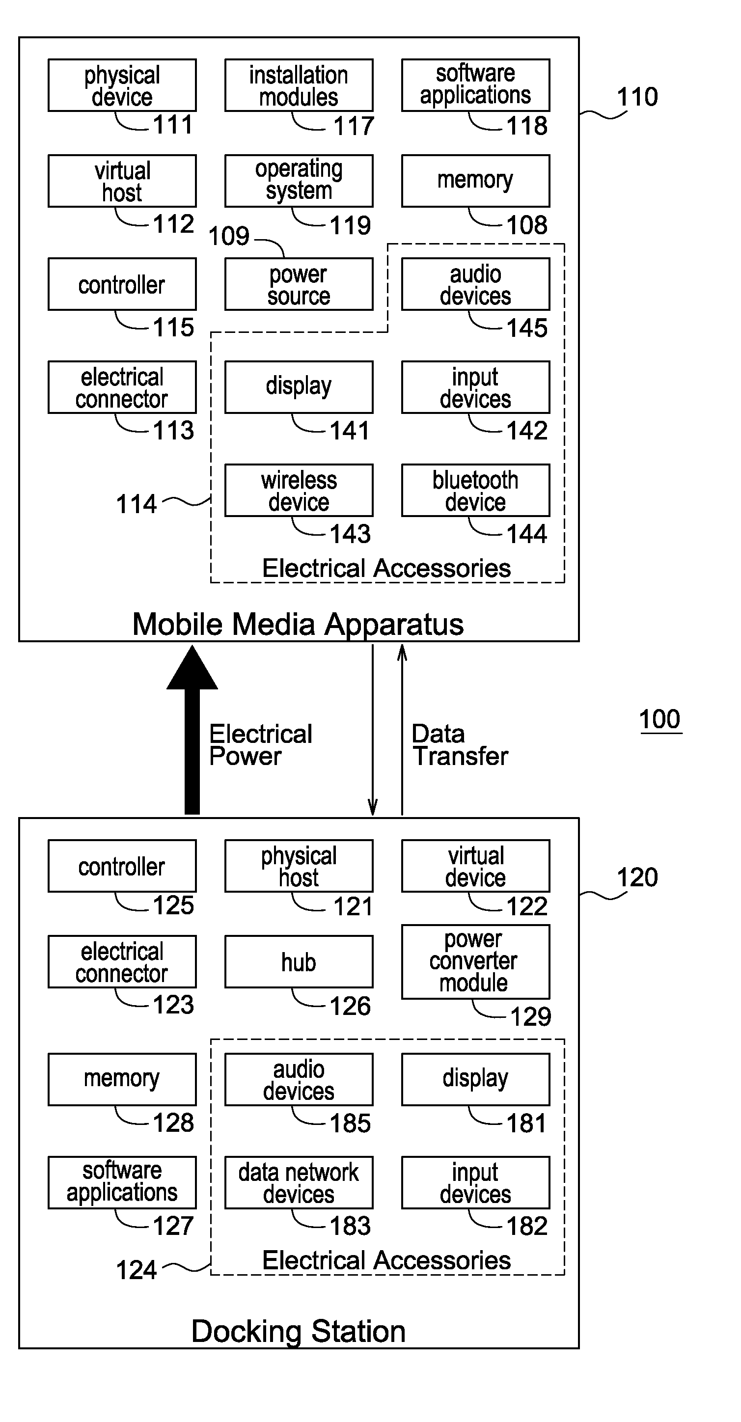
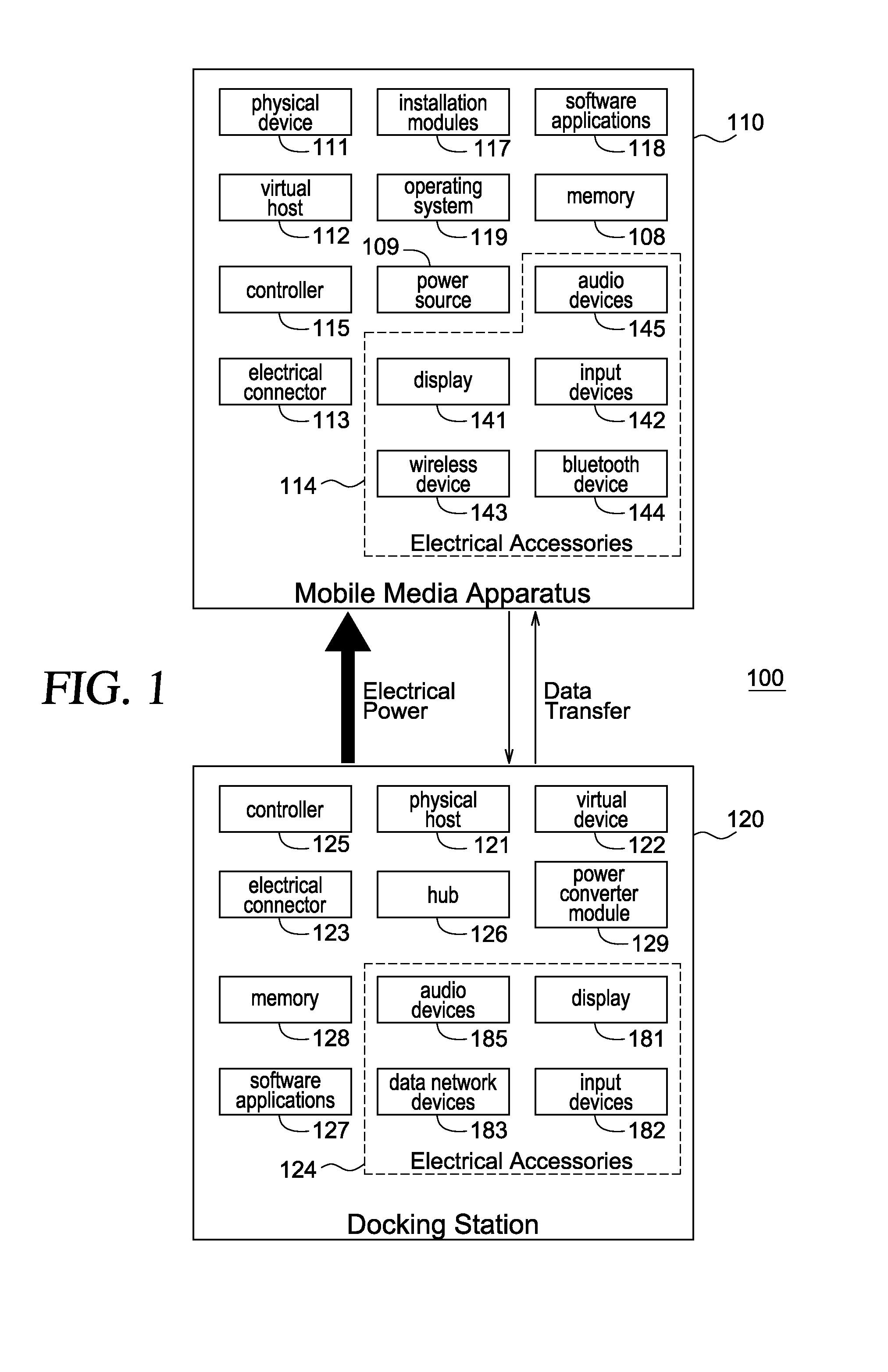
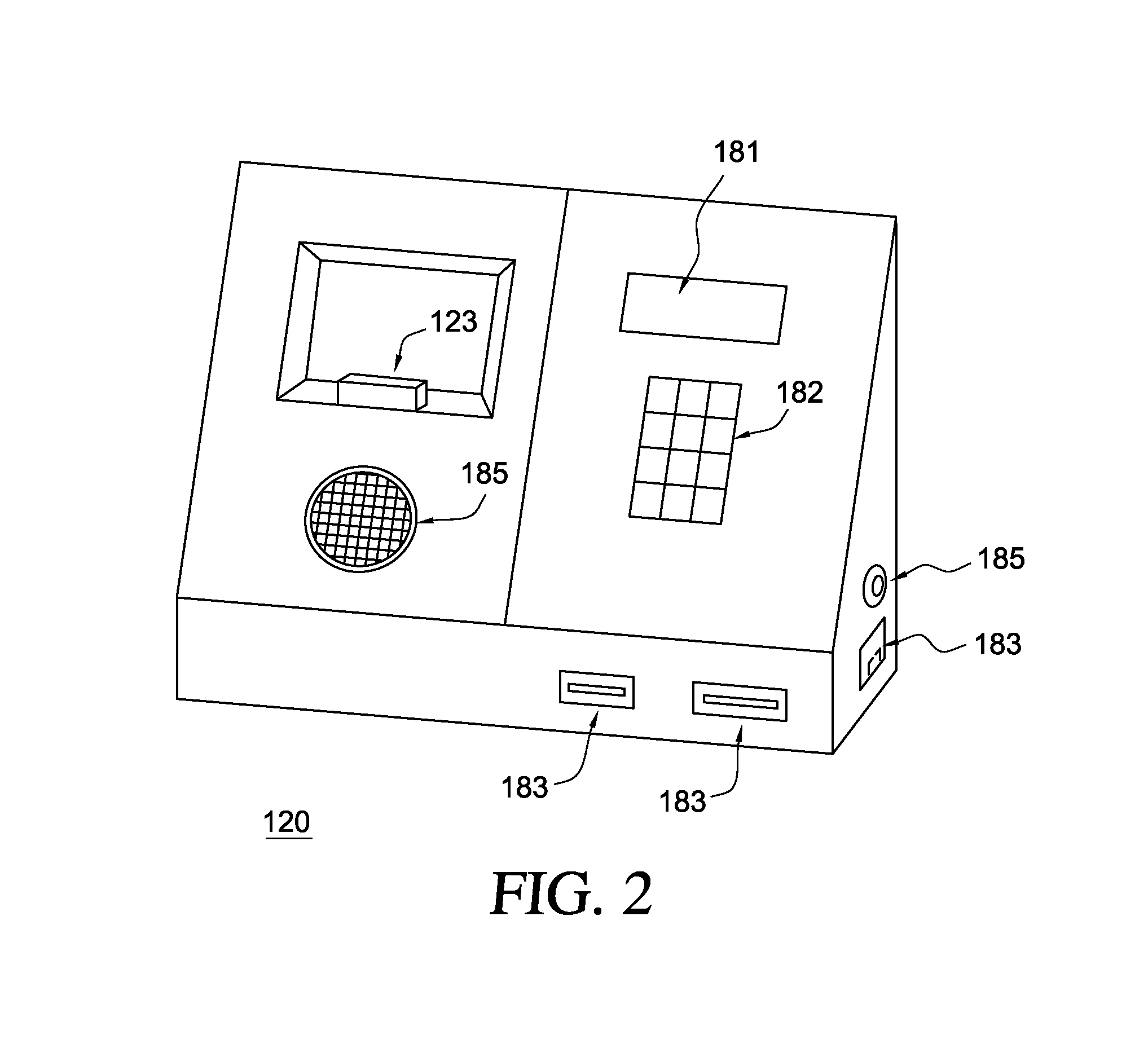
[0024]Turning to the drawings, FIG. 1 is a block diagram illustrating a system 100 of communicating between a mobile media apparatus 110 and a docking station 120, according to a System 100 is a communications system that allows mobile media apparatus 110 to act as a host (i.e., master) and docking station 120 to act as a device (i.e., slave) while mobile media apparatus 110 is receiving electrical power from docking station 120. Furthermore, system 100 can comply with one or more of the traditional USB specifications, even though the host is receiving electrical power from the device. System 100 is merely exemplary and is not limited to the embodiments presented herein. System 100 can be employed in many different embodiments or examples not specifically depicted or described herein. In some examples, system 100 can include: (a) at least part of mobile media apparatus 110; and (b) at least part of docking station 120.

[0025]Mobile media apparatus 110 can be configured to communicat...

second embodiment

[0094]Turning to another embodiment, FIG. 7 illustrates an interaction flow chart of a method 700 of communicating between a mobile media apparatus and a docking station, according to a Method 700 is merely exemplary and is not limited to the embodiments presented herein. Method 700 can be employed in many different embodiments or examples not specifically depicted or described herein. In some embodiments, the activities, the procedures, and / or the processes of method 700 can be performed in the order presented. In other embodiments, the activities, the procedures, and / or the processes of the method 700 can be performed in any other suitable order. In still other embodiments, one or more of the activities, the procedures, and / or the processes in method 700 can be combined or skipped.

[0095]Referring to FIG. 7, method 700 includes an activity 730 of starting the virtual device. In some examples, activity 730 can be similar to procedure 551 of activity 332 in FIG. 5.

[0096]Next, method...


PUM


Abstract

In some embodiments, a system can be configured to communicate to and from a media device. The media device can include a first controller. The system can include: (a) a software module configured to run on the first controller; (b) a physical device module configured to run on the first controller; (c) a virtual host module configured to run on the first controller; and (e) a docking station having: (1) a second controller; (2) an electrical connector configured to couple to the media device; (3) a physical host module configured to run on the second controller; (4) a virtual device module configured to run on the second controller; and (5) one or more accessory devices configured to communicate with the media device using the virtual device module. In some examples, the physical host module and the physical device module are configured to establish a physical communications pipe between the media device and the docking station. The virtual host module and the virtual device module can be configured to establish a virtual communications pipe between the media device and the docking station using the physical communications pipe. Other embodiments are disclosed.

Description

CROSS-REFERENCE TO RELATED APPLICATIONS[0001]This application claims the benefit of U.S. Provisional Application No. 61 / 376,435, filed Aug. 24, 2010. U.S. Provisional Application No. 61 / 376,435 is incorporated herein by reference.FIELD OF THE INVENTION[0002]This invention relates generally to systems for communicating between two electrical devices, and relates more particularly to methods of communication between two electrical devices and to systems configured to allow a first electrical device of the two electrical devices to control the communications between the two electrical devices while a second electrical device of the two electrical devices provides electrical power to the first electrical device.DESCRIPTION OF THE BACKGROUND[0003]When universal serial bus (USB) connectors of a first and second electrical apparatus are coupled together, the first electrical apparatus can provide electrical power to the second electrical apparatus. Under traditional USB specifications (e.g...

Claims


Application Information

Patent Timeline
Patent Type & Authority Applications(United States)
IPC IPC(8): G06F13/00
CPCG06F13/385
Inventor IVERSON, KENTVAN HARLINGEN, BRIANGALE, VANNINKELLY, FRANKNORTON, JOHN M.
Owner BELKIN INT
Why Eureka
Try Eureka