
Method and system for analyzing optical signal

a technology of optical signal and optical signal, applied in the field of optical signal analysis, can solve the problems of excessive photic stimulation of channel protein, inability to correct signal analysis, and extreme types of usable fluorescent probes, and achieve the effect of monitoring easily and correctly

Inactive Publication Date: 2012-03-01
OLYMPUS CORP
View PDF6 Cites 0 Cited by
  • Summary
  • Abstract
  • Description
  • Claims
  • Application Information

AI Technical Summary

Benefits of technology

The present invention provides a method and system for analyzing optical signals in an organism sample. This method uses a luminescent probe to monitor a signal protein induced by a photosensitive protein, which is activated by a stimulus light. The method and system can easily and correctly monitor the signal protein without interference caused by the excitation light of a fluorescent probe. The invention has advantages in analyzing signal proteins and can be used in various fields such as research and medical diagnosis.

Problems solved by technology

That is, excitation light of a fluorescent probe simultaneously acts also for photic stimulation of a channel protein (initiator protein) so that photic stimulation of the channel protein becomes excessive, making a correct signal analysis impossible.
Moreover, when monitoring a transcription factor, while fluorescent probes of various excitation wavelengths caused to bind to the transcription factor exist, types of usable fluorescent probes are extremely limited because the wavelength band used for photic stimulation of a channel protein cannot be used and thus, for example, fluorescent probes such as DsRed that cause excitation in the wavelength band of orange cannot be used.

Method used


Image

  • Method and system for analyzing optical signal
  • Method and system for analyzing optical signal

Examples


first embodiment

[0038]FIG. 1

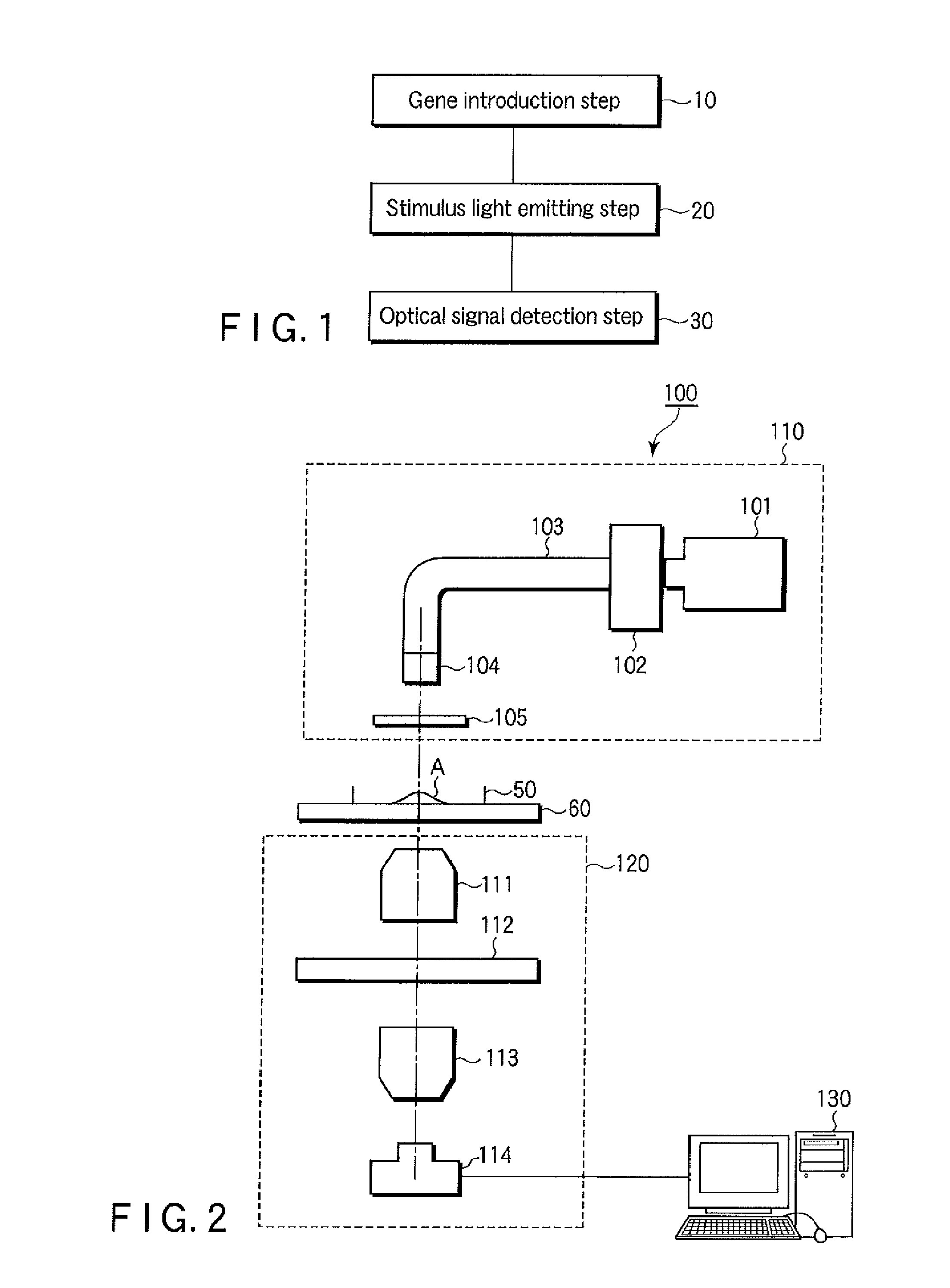
[0039]FIG. 1 is a flow chart of a method of analyzing an optical signal in the first embodiment.

[0040]The first embodiment is, as an assumption, a method of analyzing an optical signal which analyzes a signal protein induced by a photosensitive protein (hereinafter, also called a target signal protein).

[0041]The photosensitive protein used in the first embodiment means various kinds of proteins activated by photic stimulation of a specific wavelength. Examples of the photosensitive protein include a photosensitive channel protein in which depolarization and hyperpolarization of a channel (that is, opening / closing of a channel) are caused by photic stimulation of a specific wavelength and include, but are not limited to, a photosensitive ion channel film protein derived from green algae such as channel rhodopsin-2 (ChR2) and halorhodopsin (NpHR).

[0042](1) Gene Introduction Step

[0043]First, a gene that expresses a luminescent probe to analyze a target signal protein is int...

second embodiment

[0057]As the second embodiment, two target signal proteins or more to be analyzed may be present.

[0058]When, for example, two target signal proteins (first and second signal proteins) are detected, a gene to express a first luminescent probe (first luminescent probe gene) to analyze the first signal protein and a gene to express a second luminescent probe (second luminescent probe gene) to analyze the second signal protein are introduced into an organism sample. The first and second luminescent probe genes code luminescent probes emitting lights of mutually different wavelengths, and light emitted by each luminescent probe is identified as a different optical signal so that the light can individually be imaged and quantified.

[0059]The first and second signal proteins are imaged by the first and second luminescent probes respectively and thus, expressions of each signal protein and each luminescent probe need to be mutually linked.

[0060]When, for example, calcium ions (first signal t...


PUM

PropertyMeasurementUnit
color temperatureaaaaaaaaaa
photosensitiveaaaaaaaaaa

Abstract

The present invention is related to a method of analyzing an optical signal which analyzes a signal substance induced by a photosensitive protein, includes the steps of introducing a gene which expresses a luminescent probe to analyze the signal substance into an organism sample, emitting a stimulus light to activate the photosensitive protein, and detecting an optical signal emitted by the organism sample.

Description

CROSS-REFERENCE TO RELATED APPLICATIONS[0001]This application is a divisional of U.S. patent application Ser. No. 12 / 724,795, filed on Mar. 16, 2010, which is based upon and claims the benefit of priority from prior Japanese Patent Application No. 2009-071577, filed Mar. 24, 2009, the entire contents of each of which are incorporated herein by reference.BACKGROUND OF THE INVENTION[0002]1. Field of the Invention[0003]The present invention relates to a method of analyzing an optical signal which analyzes a signal substance, for example, a signal protein induced by a photosensitive protein.[0004]2. Description of the Related Art[0005]A signal protein is a protein group constituting a series of reaction systems initiated by activation of a specific protein (hereinafter, also referred to as an initiator protein) such as a receptor. A gene that determines a phenotype (hereinafter, also referred to as a phenotypic determination gene) such as a pathological gene is expressed in the end afte...

Claims


Application Information

Patent Timeline
Patent Type & Authority Applications(United States)
IPC IPC(8): C12Q1/66C12Q1/02G01N33/50
CPCC12Q1/6897C12Q2523/313C12Q2563/103A61P43/00
Inventor SUZUKI, HIROBUMI
Owner OLYMPUS CORP
Learn More