Physical quantity sensor

a sensor and physical technology, applied in the field of physical quantity sensors, can solve the problems of sensor sensitivity decline, sensor's life cannot be effectively prolonged, beam portion may not be able to return to its original stationary state, etc., and achieve the effect of preventing protrusion breakage, high sensor sensitivity, and small size and thickness

Inactive Publication Date: 2012-03-08
ALPS ALPINE CO LTD
View PDF28 Cites 9 Cited by
  • Summary
  • Abstract
  • Description
  • Claims
  • Application Information

AI Technical Summary

Benefits of technology

[0038]In this case, when the movable portion contacts or the leg portions contact the protrusions, a reaction force is uniformly applied to the protrusions, and breakage of the protrusions can be appropriately prevented.
[0039]With the configurations according to the present invention, a physical quantity sensor having a considerably small size and thickness, high sensor sensitivity, and good anti-sticking characteristics can be provided.

Problems solved by technology

However, if a large physical quantity acts on the movable portion or if a physical quantity acts on the movable portion for a long time, the beam portion may become overloaded, so that damage or the like may be caused to the beam portion or the beam portion may not be able to recover to its original stationary state even when the action of the physical quantity disappears.
Accordingly, the sensor sensitivity tends to decrease, and the sensor's life could not be effectively prolonged.
However, the structure described Japanese Unexamined Patent Application Publication No. 2005-283393 is a complex structure in which a step is formed on a surface of the weight in a height direction and the weight stopper faces a recessed portion of the weight in the height direction.
It is very difficult to form this structure by using MEMS technology.
With the existing structure described above, movement of the movable portion is unstable and fluctuating and deformation of the beam portion in the height direction is hindered, so that it was difficult for the movable portion to perform translational motion in the height direction in a stable manner and it is not possible to obtain precise sensor sensitivity.
However, it was difficult to precisely form a sticking prevention structure composed of, for example, protrusions, on the movable portion or on the facing surface that faces the movable portion.
Even with the configurations described in Japanese Unexamined Patent Application Publication Nos. 2005-283393 and 2008-197113, the stopper and the weight tend to surface-contact each other, and sticking tends to occur.

Method used


Image

  • Physical quantity sensor
  • Physical quantity sensor
  • Physical quantity sensor

Examples


Embodiment Construction

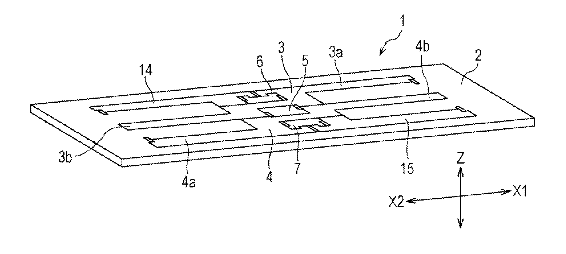
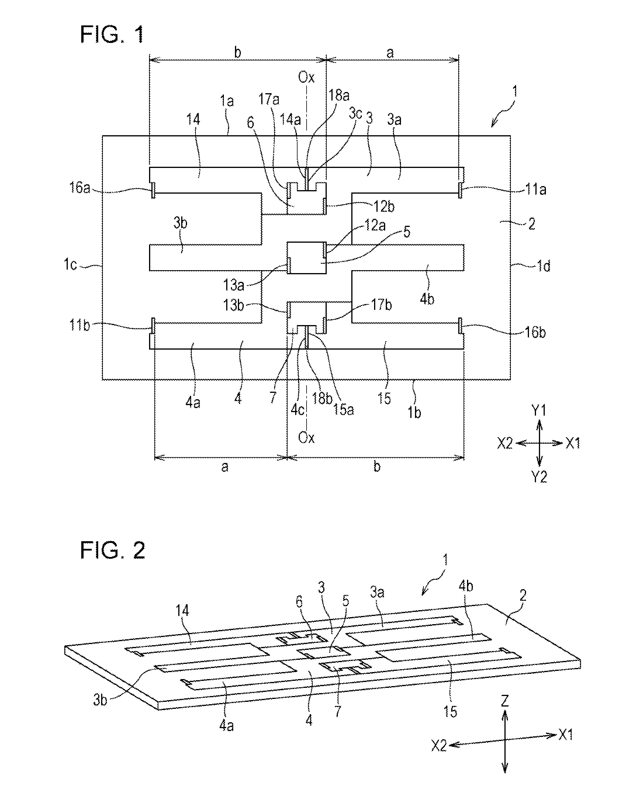
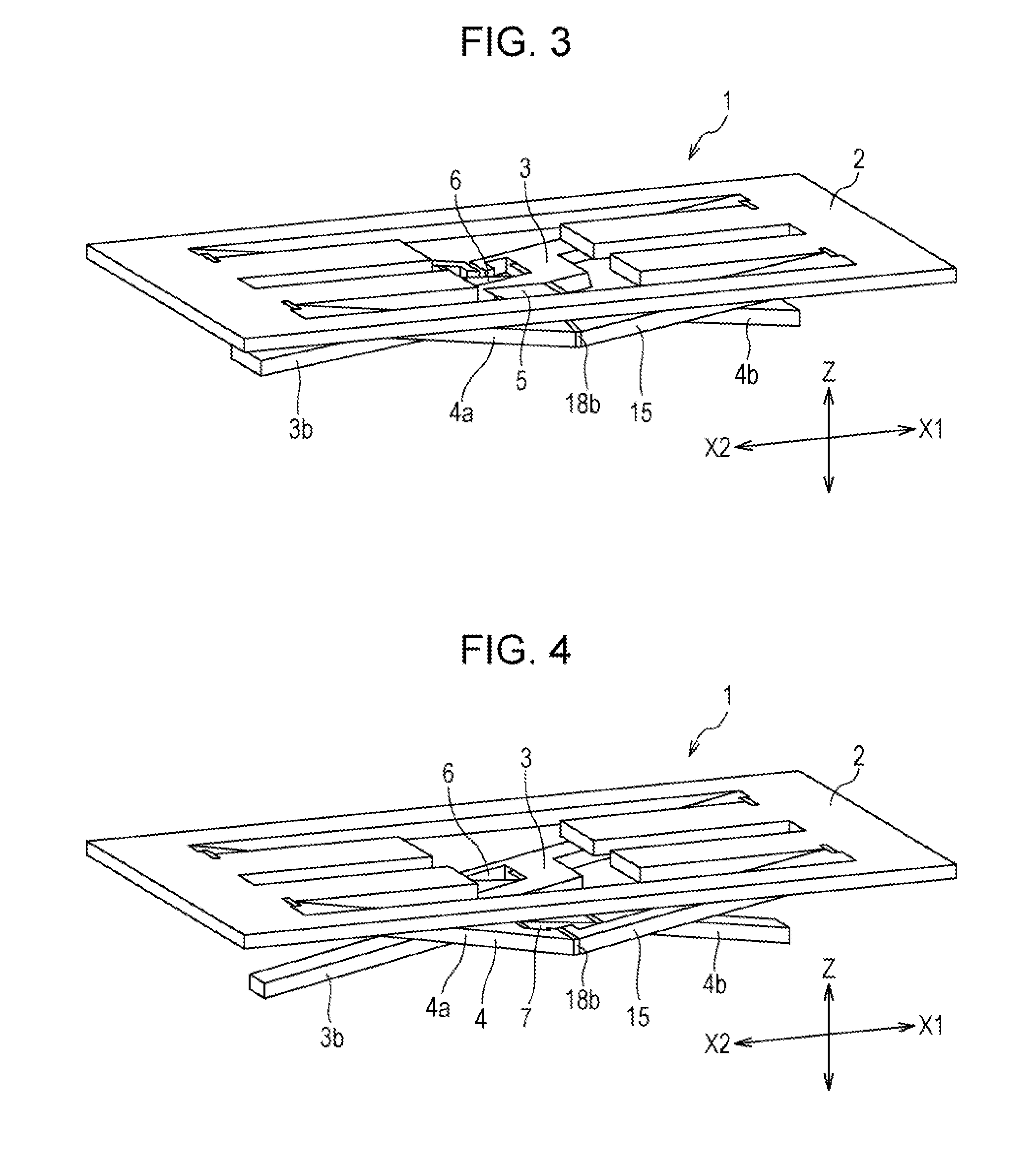
[0060]Regarding physical quantity sensors illustrated in the drawings, the Y direction is the left-right direction, the Y1 direction is the leftward direction, the Y2 direction is the rightward direction, the X direction is the front-back direction, the X1 direction is the forward direction, and the X2 direction is the backward direction. The up-down direction (Z direction; height direction) is a direction that is perpendicular to both the Y direction and the X direction.

[0061]A physical quantity sensor 1 illustrated in FIG. 1 is made of, for example, a silicon substrate having a rectangular plate-like shape. That is, resist layers having planar shapes corresponding to the shapes of components are formed on a silicon substrate, and the components are formed so as to be separated from one another by cutting the silicon substrate at portions at which the resist layers are not present through an etching process such as deep RIE (deep reactive ion etching). Therefore, the components of ...


PUM


Abstract

A physical quantity sensor includes an anchor portion, a movable portion displaceable in a height direction, a supporting portion rotatably connected to the anchor portion and the movable portion, and a detection portion. The supporting portion includes a first connection arm connecting the anchor portion and the movable portion to each other and a leg portion extending from the anchor portion in a direction opposite to the first connection arm, the leg portion being displaced in a direction opposite to a displacement direction of the movable portion when the supporting portion rotates. A stopper surface is disposed at a position to which a distal end portion of the leg portion is contactable when the leg portion is displaced in the direction opposite to the displacement direction of the movable portion. Displacement of the movable portion is restricted when the distal end portion of the leg portion contacts the stopper surface.

Description

CLAIM OF PRIORITY[0001]This application is a Continuation of International Application No. PCT / JP2010 / 058336 filed on May 18, 2010, which claims benefit of Japanese Patent Application No. 2009-133981 filed on Jun. 3, 2009 and No. 2009-199146 filed on Aug. 31, 2009. The entire contents of each application noted above are hereby incorporated by reference.BACKGROUND OF THE INVENTION[0002]1. Field of the Invention[0003]The present invention relates to a physical quantity sensor that is capable of measuring a physical quantity, such as acceleration, applied from the outside by detecting a displacement amount of a movable portion that is formed by, for example, cutting from a silicon substrate.[0004]2. Description of the Related Art[0005]For example, a physical quantity sensor includes a movable portion that is made by etching a silicon substrate and that is supported so as to be movable in the height direction. In such a case, for example, in a structure described in Japanese Unexamined ...

Claims


Application Information

Patent Timeline
Patent Type & Authority Applications(United States)
IPC IPC(8): G01P15/125
CPCB81B3/001B81B3/0021G01P15/08G01P2015/0871G01P15/125G01P2015/0837G01P15/0802
Inventor MIYATAKE, AKIRATAKAHASHI, TORUOHKAWA, HISANOBUKIKUIRI, KATSUYAYAZAWA, HISAYUKIKOBAYASHI, TOSHIHIROUTO, YOSHITAKA
Owner ALPS ALPINE CO LTD
Why Eureka
Try Eureka