Foldable tent with integrated ventilation system

a ventilation system and tent technology, applied in tents/canopies, building types, constructions, etc., can solve the problems of increased labor, additional manufacturing costs, and instant tents of umbrella types, and achieve the effect of improving ventilation and simply opening and closing

Inactive Publication Date: 2012-03-08
JIN KI HO
View PDF9 Cites 20 Cited by
  • Summary
  • Abstract
  • Description
  • Claims
  • Application Information

AI Technical Summary

Benefits of technology

[0010]The present invention is intended to overcome at least the above-described disadvantages and to provide further improvements to instant tents in the prior art. The objects and advantages of the present invention, more specifically, are to provide instant tents with improved ventilation at all times including when the windows and doors are closed, and during inclement weather conditions; and to provide a rain fly integral to the instant tent such that the user could simply open and close the tent without having to attach additional components to the instant tent.

Problems solved by technology

Umbrella type instant tents, however, are problematic for a number of reasons which include but are not limited to: (1) the additional costs in manufacturing due to the parts required for the tent, i.e., the central shaft, sub-braces and locking mechanism, as well as increased labor to assemble those parts; (2) the increased potential for failure and necessary repair of the central shaft, sub-braces and locking mechanism; and (3) the increased size and weight of the tent due to the extra components.
First, tents in general lack sufficient ventilation.
Moreover, condensation can develop due to the lack of air circulation.
Even though tents are commonly equipped with screen windows or doors on one or more sides of the tent, it is difficult to achieve sufficient ventilation unless a wind or draft is blowing directly into an open window or door and out another open window or door.
Furthermore, when a user wishes to close the windows or doors for other reasons such as for safety or privacy it is difficult to ventilate the interior of the tent.
Second, even though some instant tents are sold with a separate cover or fly to protect the tent from adverse weather conditions such as rain, sleet or snow, or to provide shade from the sun light, the cover or fly is not integrated with the instant tent and, thus, the user is required to separately attach and detach the cover or fly to and from the instant tent.
In addition, because the rain fly typically covers most of the tent including the windows, it is not possible to achieve proper ventilation.

Method used


Image

  • Foldable tent with integrated ventilation system
  • Foldable tent with integrated ventilation system
  • Foldable tent with integrated ventilation system

Examples


first embodiment

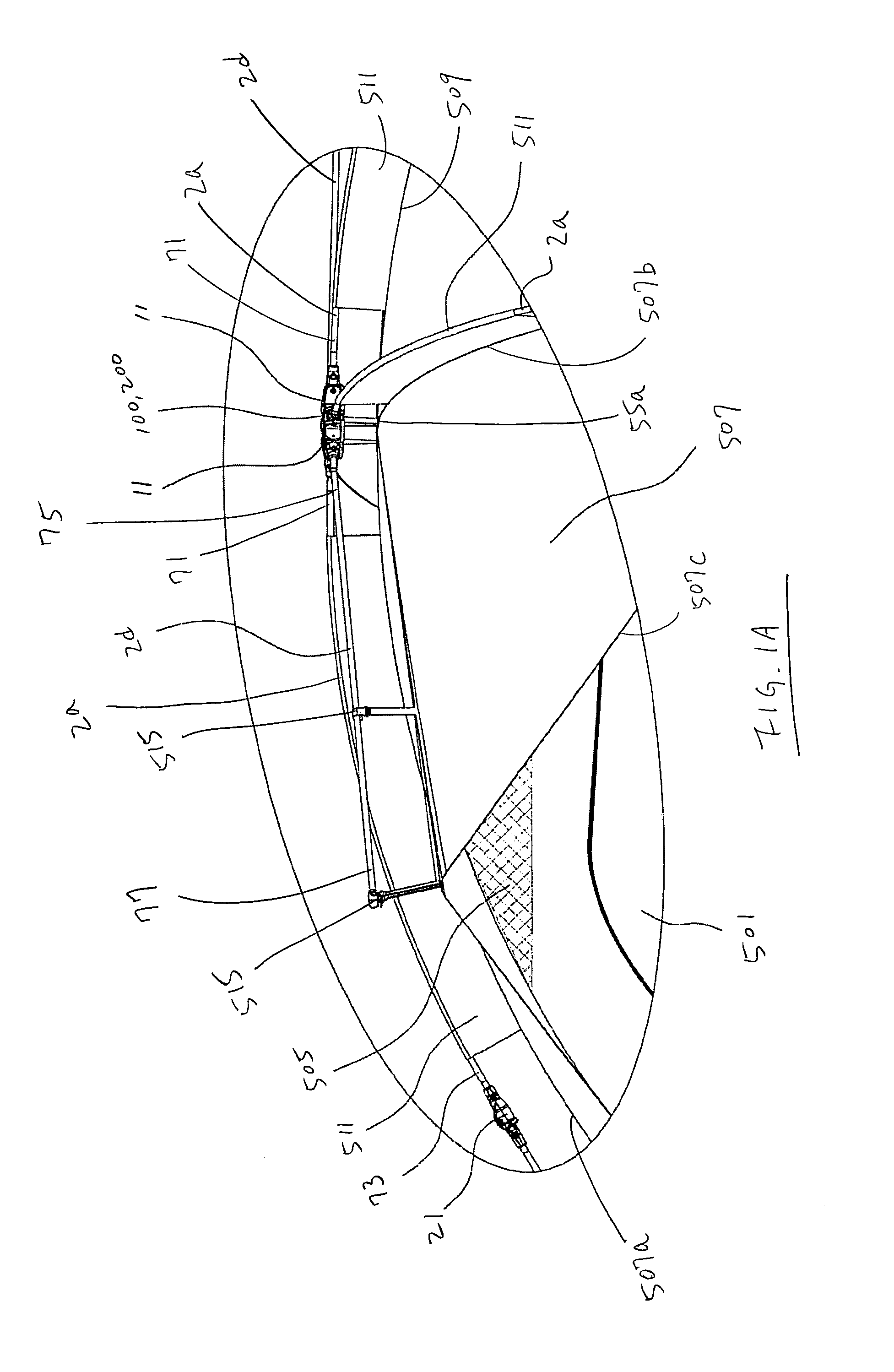
[0041]In the first embodiment, shown in FIG. 6, the base 12 uniformly extends radially and provides a surface 12a below the pivoting pins 4 and caps 3 so that the first ends of each roof pole and eave pole 71, 75 can pivot to and from the open and closed configurations within each corresponding slot 11. The base 12 is extended to cover the area under the caps 3 to relieve the stresses exerted on the roof poles 2a but one of ordinary skill in the art will recognize that the base 12 need not extend fully to provide a surface to cover the entire length of the caps 3.

second embodiment

[0042]Referring to FIGS. 8A-D, in the second embodiment, the base 12 extends radially outward except that the base 12 does not extend above the radially outer portions of the slots 11 where the caps 3 are pivotally connected to the walls 51, thereby forming an opening or a void 61. Thus, in the open configuration, as shown in FIG. 8D, the bottom surface of the base 12b restricts the caps 3 and first ends of each the roof pole and eave pole 71, 75 from any upward pivotal movement beyond the bottom surface of the base 12b. As a result, the roof pole and eave pole first ends 71, 75 are secured in a substantially horizontal position or substantially parallel to the bottom surface of the base 12b. Referring to FIG. 11A, in the closed configuration, the opening 61 provided on the radially outer portions of the slots 11 allow the pole second ends 73, 77 to pivotally move upward while all or a substantial portion of the caps 3 located at the pole first ends 71, 75 remain below a horizontal ...


PUM


Abstract

The present invention provides an instant tent with an integral vent and corresponding rain fly for providing the tent with continuous ventilation while protecting the vent and interior of the tent from adverse weather conditions. The frame of the tent includes a hub, a plurality of roof poles and eave poles pivotally coupled to the hub, and a plurality of leg poles coupled to the corresponding roof poles. Coupled to the frame is an enclosed canopy which includes the vent at a top portion of the canopy to allow air from continuously entering and exiting the interior of the tent. The rain fly is attached to the canopy and corresponding eave pole, and is disposed proximate the vent. Thus, the instant tent of the present invention is provided with secure and continuous ventilation, and is opened and closed without requiring additional assembly of components.

Description

[0001]This application is a continuation-in-part of U.S. patent application Ser. No. 12 / 658,473 filed on Feb. 4, 2010, which is incorporated by reference in its entirety.BACKGROUND OF THE INVENTION[0002]1. Field of the Invention[0003]The present invention relates to a foldable tent and more particularly to an instant tent with an integrated ventilation system and rain fly.[0004]2. Description of Prior Art[0005]For novice campers, foldable tents are a popular alternative to conventional assemble-to-use tents. Foldable tents, which are commonly referred to as “instant tents,”“one-touch tents” or “pop-up tents,” are sold preassembled, making opening and closing of the tent easy and less time consuming.[0006]Instant tents are sold in several different designs. One type of instant tent, for example, is manufactured and sold as a structure similar to that of a conventional umbrella as shown, for example, in U.S. Pat. No. 6,581,617. In those structures, the tent is opened and collapsed by ...

Claims


Application Information

Patent Timeline
Patent Type & Authority Applications(United States)
IPC IPC(8): E04H15/48
CPCE04H15/42E04H15/46E04H15/48E04H15/14E04H15/425E04H15/36E04H15/40E04H15/405
Inventor CHOI, KWAN JUN
Owner JIN KI HO
Why Eureka
Try Eureka