Shape-changeable camera mouse

Inactive Publication Date: 2012-03-08
PRIMAX ELECTRONICS LTD
7 Cites 1 Cited by

AI-Extracted Technical Summary

Problems solved by technology

However, the mouse having the basic functions fails to meet the user's requirements.
Although the conventional camera mouse has both the functions of a camera and a mouse, there are still some drawbacks.
For example, since the shape of the camera mouse is similar to the common mous...

Method used

[0041]From the above description, the shape of the shape-changeable camera mouse of the present invention may be adjusted according to the practical requirements of the user. For using the shape-changeable camera mouse in a computer system, the shape-changeable camera mouse is operated in a mouse mode by changing the shape thereof. For using the shape-changeable camera mouse to shoot an object, the shape-changeable camera mouse is operated in a camera mode by changing the shape thereof. When the shape-changeable camera mouse is operated in the ca...

Benefits of technology

[0009]The present invention provides a shape-c...

Abstract

A shape-changeable camera mouse includes a first casing and a second casing. The first casing includes an image pickup module for shooting an object. When an included angle is defined between the first casing and the second casing, the shape-changeable camera mouse is operated in a mouse mode. Whereas, when the first casing and the second casing are parallel with each other, the shape-changeable camera mouse is operated in a camera mode.

Application Domain

Technology Topic

Image

  • Shape-changeable camera mouse
  • Shape-changeable camera mouse
  • Shape-changeable camera mouse

Examples

  • Experimental program(1)

Example

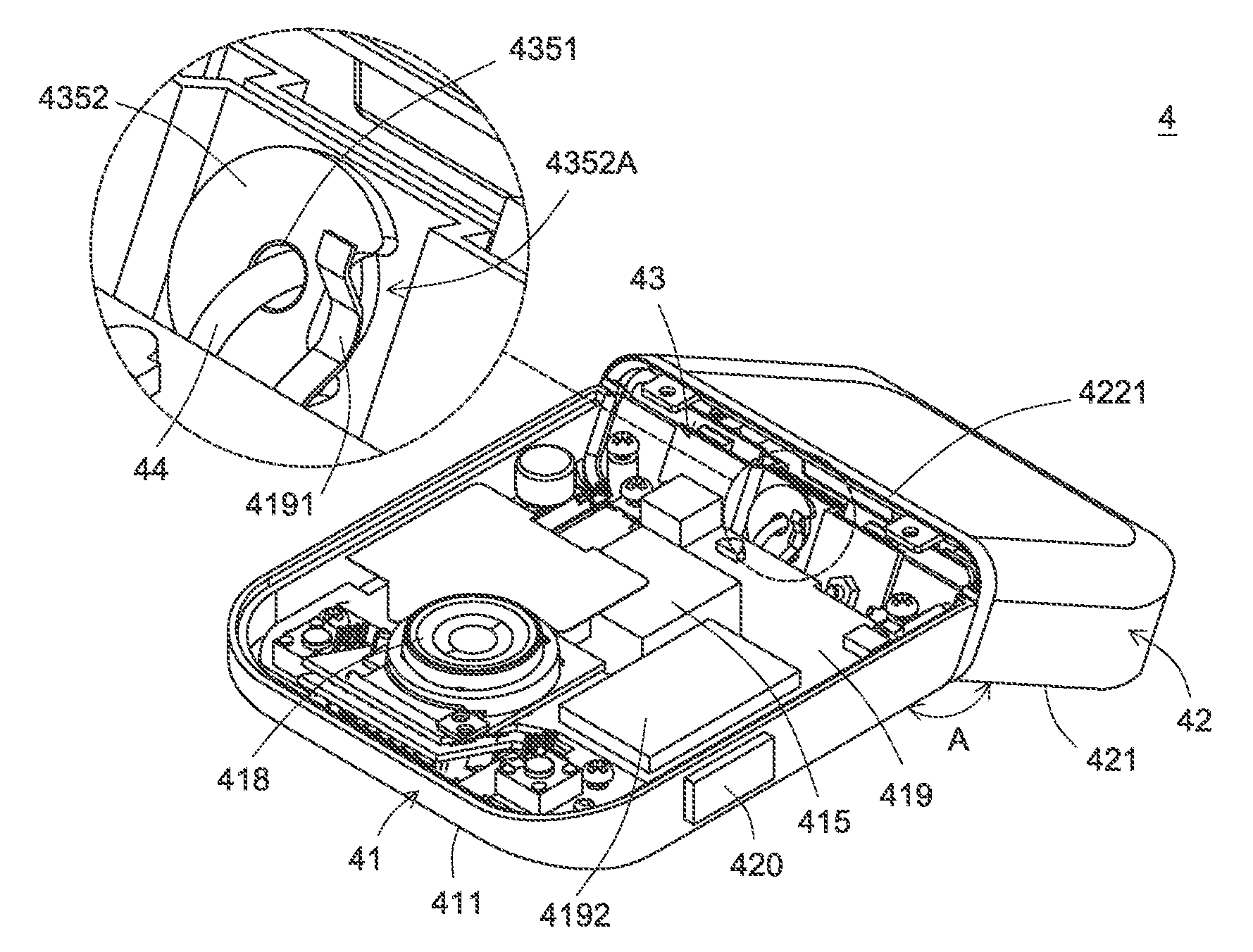
[0031]For obviating the drawbacks encountered from the prior art, the present invention provides a shape-changeable camera mouse. FIG. 4 is a schematic diagram illustrating the connection between a shape-changeable camera mouse and a computer system according to an embodiment of the present invention. As shown in FIG. 4, the shape-changeable camera mouse 4 comprises a first casing 41, a second casing 42, a wireless emitter 45 and a wireless receiver 46. The wireless emitter 45 is disposed within the first casing 41 for generating a wireless signal S. The wireless receiver 46 is connected with a computer system 5 for receiving the wireless signal S. In this embodiment, the computer system 5 is a notebook computer.
[0032]Hereinafter, the configurations of the shape-changeable camera mouse will be illustrated with reference to FIG. 5. FIG. 5 is a schematic partial exploded view illustrating the shape-changeable camera mouse according to the embodiment of the present invention. In addition to the first casing 41 and the second casing 42, the shape-changeable camera mouse 4 further comprises a connecting member 43 and a signal wire 44. The first casing 41 comprises a first lower surface 411, a first upper surface 412 (see FIG. 7) and a first slant surface 413. The first slant surface 413 is arranged at a rear side of the first casing 41. In addition, the first slant surface 413 has a first slant upper rim 4131 (see FIG. 7). The second casing 42 comprises a second lower surface 421 and a second slant surface 422. The second slant surface 422 is arranged at a front side of the second casing 42. In addition, the second slant surface 422 has a second slant upper rim 4221 (see FIG. 7) and a second slant lower rim 4222.
[0033]The connecting member 43 comprises a first supporting frame 431, a second supporting frame 432, a first metallic gasket 433, a second metallic gasket 434 and a rotating shaft 435. The first supporting frame 431 is disposed at the rear side of the first casing 41. In addition, the first supporting frame 431 has a first perforation 4311. The second supporting frame 432 is disposed at the front side of the second casing 42. In addition, the second supporting frame 432 has a second perforation 4321. The first metallic gasket 433 has a first gasket hole 4331. The second metallic gasket 434 has a second gasket hole 4341. The rotating shaft 435 successively penetrates through the first metallic gasket 433, the first supporting frame 431, the second supporting frame 432 and the second metallic gasket 434. The rotating shaft 435 has a rotating shaft hole 4351 and a rotating shaft surface 4352. In addition, a notch 4352A is formed in the rotating shaft surface 4352. Upon rotation of the rotating shaft surface 4352, the notch 4352A is moved as the rotating shaft surface 4352 is rotated. The signal wire 44 penetrates through the rotating shaft hole 4351 for establishing electrical connection between the first casing 41 and the second casing 42. That is, since the first casing 41 and the second casing 42 are connected with each other through the connecting member 43, the second casing 42 can be rotated with respect to the first casing 41 to change the shape of the shape-changeable camera mouse 4.
[0034]In accordance with a key feature of the present invention, the shape-changeable camera mouse 4 may be switched between a mouse mode and a camera mode by changing the shape of the shape-changeable camera mouse 4.
[0035]FIG. 6 is a schematic perspective view illustrating the internal portion of the shape-changeable camera mouse in a mouse mode according to an embodiment of the present invention. FIG. 7 is a schematic perspective view illustrating the external appearance of the shape-changeable camera mouse of FIG. 6. Please refer to FIGS. 6 and 7. In addition to the casing surface, the first casing 41 of the shape-changeable camera mouse 4 further comprises an optical displacement sensing element 414 (see FIG. 8), an image pickup module 415, a first button 416, a second button 417, an optical finger navigation (OFN) sensor 418, a circuit board 419 and a shooting key 420. According to the movement of the shape-changeable camera mouse 4 on a working surface, the optical displacement sensing element 414 generates a corresponding displacement amount. The image pickup module 415 is used for shooting an object to acquire an image. The first button 416 is disposed on the first upper surface 412 of the first casing 41. The second button 417 is disposed on the first upper surface 412, and arranged beside the first button 416. In this embodiment, the first button is a left button, and the second button 417 is a right button. The optical finger navigation sensor 418 is disposed on the circuit board 419, exposed to the first upper surface 412, and arranged between the first button 416 and the second button 417. The use of the optical finger navigation sensor 418 may provide a function of scrolling a graphic-based window shown on the computer monitor.
[0036]Please refer to FIGS. 6 and 7 again. The circuit board 419 is disposed within the first casing 41. The optical displacement sensing element 414, the image pickup module 415 and the optical finger navigation sensor 418 are mounted on the circuit board 419. The signal wire 44 penetrates through the rotating shaft hole 4351 to be electrically connected with the circuit board 419. In addition, a resilient slice 4191 and a controlling unit 4192 are also disposed on the circuit board 419. In a case that the shape-changeable camera mouse 4 is operated in the mouse mode, the resilient slice 4191 is inserted into the notch 4352A but not contacted with the rotating shaft surface 4352. Whereas, in a case that the shape-changeable camera mouse 4 is operated in a camera mode, the notch 4352A is correspondingly moved and thus the resilient slice 4191 is contacted with the rotating shaft surface 4352. The controlling unit 4192 is connected with the resilient slice 4191 through the circuit board 419. By judging whether the resilient slice 4191 is contacted with the rotating shaft surface 4352 or not, the controlling unit 4192 may realize that the shape-changeable camera mouse 4 is operated in either the camera mode or the mouse mode. An example of the controlling unit 4192 is a microprocessor.
[0037]In a case that the shape-changeable camera mouse 4 is operated in the mouse mode by rotating the second casing 42 with respect to the first casing 41, the first slant upper rim 4131 of the first slant surface 413 is contacted with the second slant upper rim 4221 of the second slant surface 422. Meanwhile, there is an included angle A between the first lower surface 411 of the first casing 41 and the second lower surface 421 of the second casing 42. The included angle A is smaller than 180 degrees. In particular, the included angle A is an obtuse angle. Meanwhile, a cambered surface is defined between the first casing 41 and the second casing 42 for supporting the user's palm (see FIG. 6).
[0038]By the way, when the shape-changeable camera mouse 4 is operated in the mouse mode, the resilient slice 4191 is inserted into the notch 4352A but not contacted with the rotating shaft surface 4352 (see FIG. 7). Consequently, the voltage transmitted from the resilient slice 4191 is a high logic level voltage. In response to the high logic level voltage, the controlling unit 4192 judges that the shape-changeable camera mouse 4 is operated in the mouse mode.
[0039]FIG. 8 is a schematic perspective view illustrating the external appearance of the shape-changeable camera mouse in a camera mode according to an embodiment of the present invention. FIG. 9 is a schematic perspective view illustrating the internal portion of the shape-changeable camera mouse of FIG. 8. Please refer to FIGS. 8 and 9. In a case that the shape-changeable camera mouse 4 is operated in the camera mode by rotating the second casing 42 with respect to the first casing 41, the first slant upper rim 4131 of the first slant surface 413 is contacted with the second slant lower rim 4222 of the second slant surface 422. Meanwhile, the first lower surface 411 of the first casing 41 and the second lower surface 421 of the second casing 42 are parallel with each other. In this situation, the shape-changeable camera mouse has a rectangular shape (see FIG. 8). In addition, upon synchronous of the rotating shaft 435 with the second casing 42, the notch 4352A is moved as the rotating shaft surface 4352 is rotated. Consequently, the resilient slice 4191 is contacted with the rotating shaft surface 4352. In this situation, the voltage transmitted from the resilient slice 4191 is switched from the high logic level voltage to a ground voltage. In response to the ground voltage, the controlling unit 4192 judges that the shape-changeable camera mouse 4 is operated in the camera mode.
[0040]Please refer to FIGS. 8 and 9 again. The second casing 42 further comprises a battery 423 and a display screen 424. The battery 423 is disposed within the second casing 42 for providing electricity. The display screen 424 is disposed on the second lower surface 421 of the second casing 42 for showing the image acquired by the image pickup module 415. By pressing the shooting key 420 of the first casing 41, the image pickup module 415 is triggered to shoot the object. It is noted that the image acquired by the image pickup module 415 is transmitted from the first casing 41 to the display screen 424 of the second casing 42 through the signal wire 44. Similarly, electricity may be transmitted from the battery 423 of the second casing 42 to the circuit board 419 of the first casing 41 through the signal wire 44. As a consequence, the electricity required for operating the shape-changeable camera mouse 4 is acquired by the circuit board 419.
[0041]From the above description, the shape of the shape-changeable camera mouse of the present invention may be adjusted according to the practical requirements of the user. For using the shape-changeable camera mouse in a computer system, the shape-changeable camera mouse is operated in a mouse mode by changing the shape thereof. For using the shape-changeable camera mouse to shoot an object, the shape-changeable camera mouse is operated in a camera mode by changing the shape thereof. When the shape-changeable camera mouse is operated in the camera mode, the shape-changeable camera mouse may be used to shoot an object to acquire an image, and the acquired image may be shown on the display screen. In addition, when the shape-changeable camera mouse of the present invention is operated in the camera mode, the shape-changeable camera mouse has a flat rectangular shape similar to the common camera. Since the shape-changeable camera mouse having the flat rectangular shape may be placed in the coat pocket or the trouser pocket of the user, the shape-changeable camera mouse is easily carried.
[0042]While the invention has been described in terms of what is presently considered to be the most practical and preferred embodiments, it is to be understood that the invention needs not be limited to the disclosed embodiment. On the contrary, it is intended to cover various modifications and similar arrangements included within the spirit and scope of the appended claims which are to be accorded with the broadest interpretation so as to encompass all such modifications and similar structures.

PUM

no PUM

Description & Claims & Application Information

We can also present the details of the Description, Claims and Application information to help users get a comprehensive understanding of the technical details of the patent, such as background art, summary of invention, brief description of drawings, description of embodiments, and other original content. On the other hand, users can also determine the specific scope of protection of the technology through the list of claims; as well as understand the changes in the life cycle of the technology with the presentation of the patent timeline. Login to view more.

Similar technology patents

Tape measure

InactiveUS20070101599A1Easily carryMaximize it standoutMeasuring tapesTape measureEngineering
Owner:BLACK & DECKER INC

Combination nail polish remover and applicator bottle

ActiveUS20110088710A1Quickly and easily be separateEasily carryCapsWriting implementsSolventApplicator Bottle
Owner:GRACE BEAUTY S R O

Classification and recommendation of technical efficacy words

Why Eureka
Try Eureka