Protective helmet; Method for mitigating or preventing a head injury

a protective helmet and head technology, applied in protective equipment, protective gear, hats, etc., can solve the problems of round helmets, no protection, no success on the market, etc., and achieve the effect of mitigating or preventing a head injury

Inactive Publication Date: 2012-03-15
SCHIMPF OLIVER
View PDF21 Cites 145 Cited by
  • Summary
  • Abstract
  • Description
  • Claims
  • Application Information

AI Technical Summary

Benefits of technology

[0006]In contrast, the protective helmet according to the invention and the method according to the invention provide for mitigating or preventing a head injury, and has the advantage that, by dividing the shock-absorbing, or shock-absorbing and comfort-providing, inner wearing unit, which can comprise liners, comfort pads, protective pads, nubbed cages and / or strapped wearing units (for example spider-shaped wearing elements, wearing straps, head bands or the like), into a shell-side insert and a head-side insert, which can be counter-rotated (preferably starting from application of a predetermined force) in at least one direction, a sliding surface is provided that assumes the function of a rotational surface, so that the angular acceleration introduced by a blow is drastically reduced or prevented, because the head-side insert and the shell-side insert, and thus the head of the wearer and the outer helmet shell, can be counter-rotated quickly and without impediment, preferably in all directions. The division can relate to the shock-absorbing and / or the non-shock-absorbing part of the inner wearing unit.

Problems solved by technology

Round helmets which, as seen looking from the front, appear to be wide, are not successful on the market.
The disadvantage of these protective helmets is that, while they offer protection from blows striking the protective helmet or the bump cap thereof translatorily, they offer no protection from rotatory forces acting during the blow, so that, for example, many accidents result in severe head injuries despite the use of a protective helmet.
It must be regarded as disadvantageous that the outward appearance of the protective helmet is negatively influenced by the skin.
The disadvantage of this solution is that the rotary motion is inhibited by the oval shape of the helmet in the general form thereof.
Thus, good protective action is achieved, but this solution is very complex.

Method used


Image

  • Protective helmet; Method for mitigating or preventing a head injury
  • Protective helmet; Method for mitigating or preventing a head injury
  • Protective helmet; Method for mitigating or preventing a head injury

Examples


first embodiment

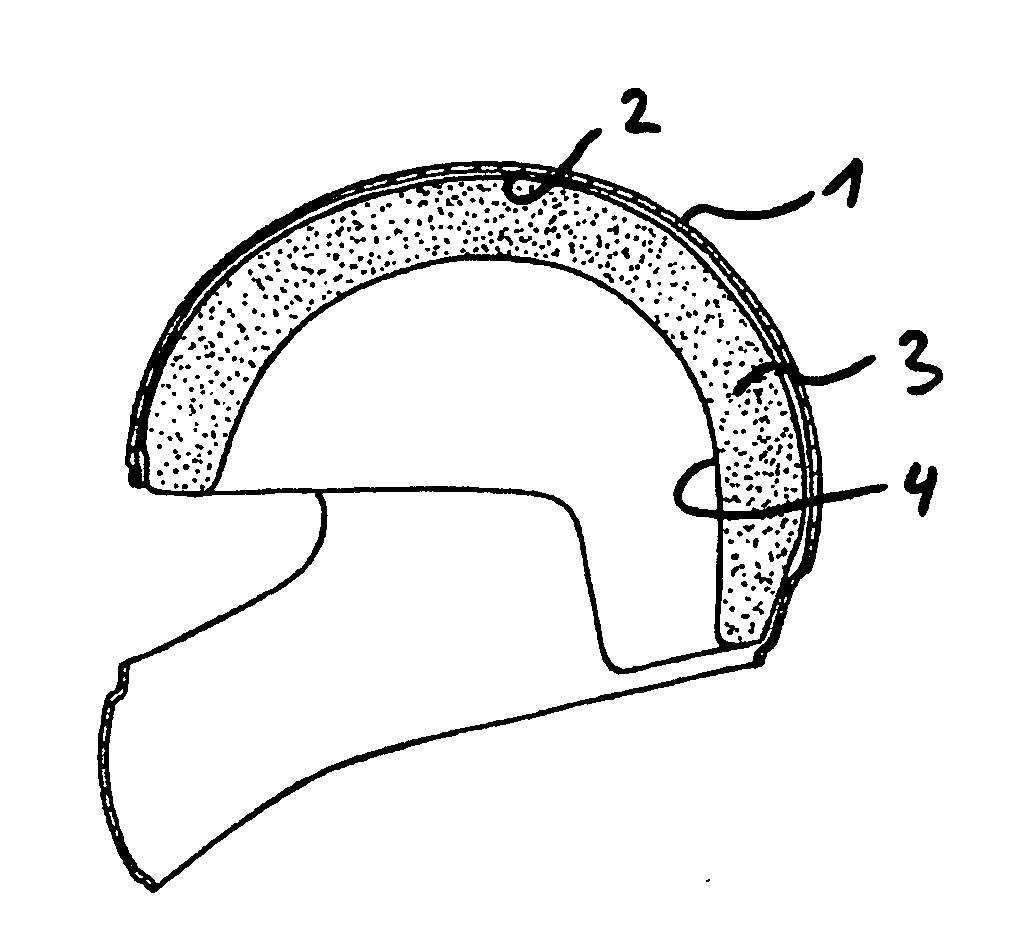
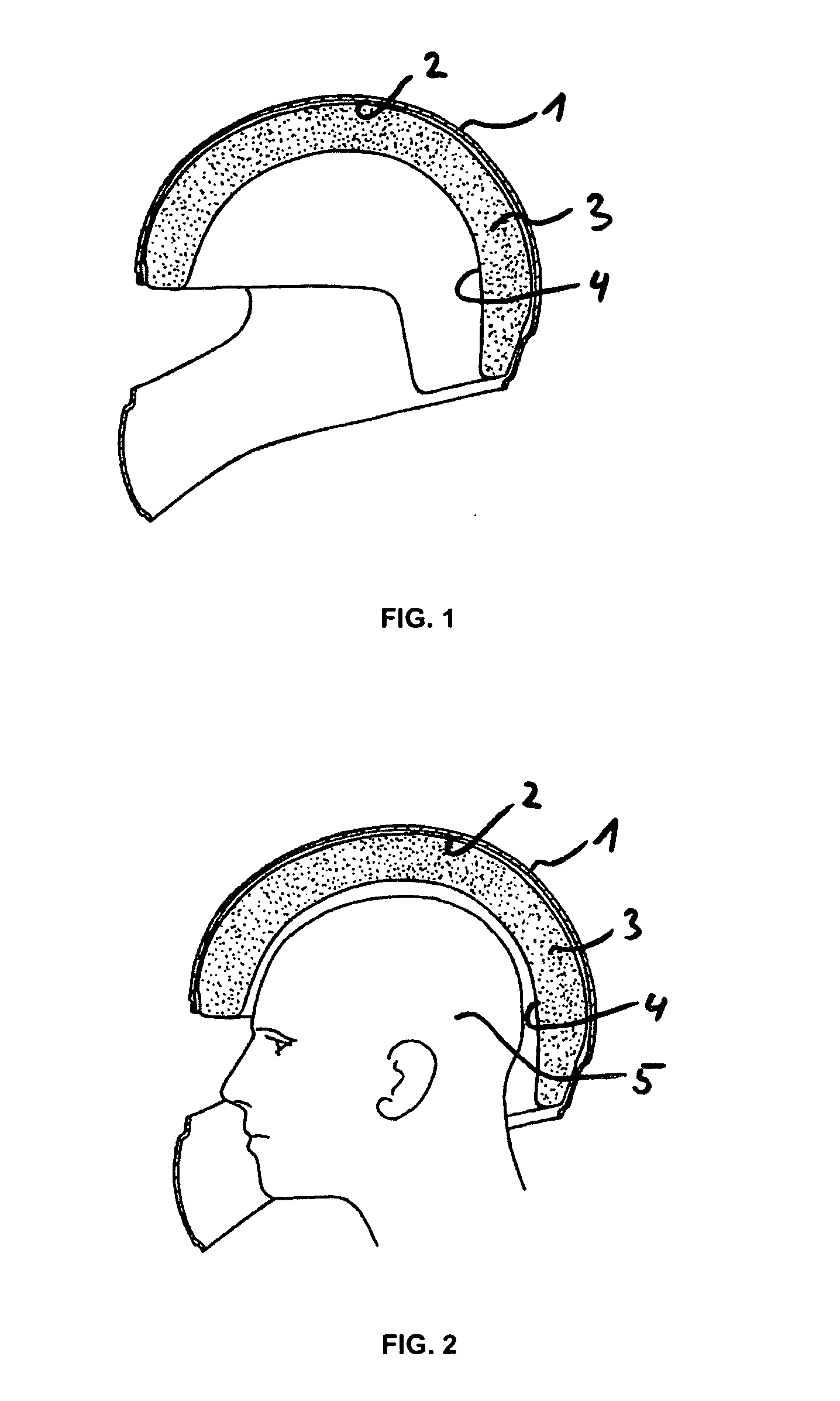
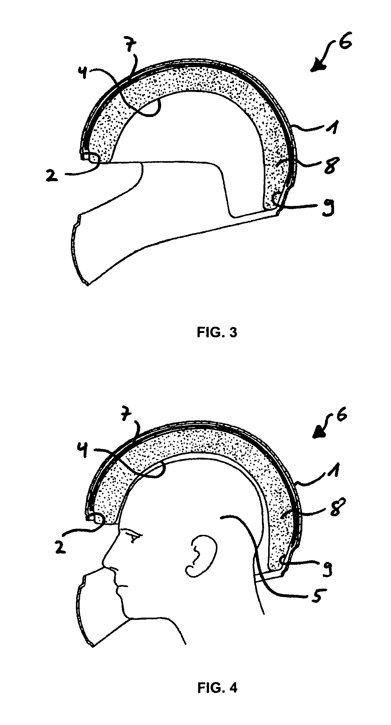
[0053]FIG. 3 and FIG. 4 show sectional views of a protective helmet 6 according to the invention. The shock-absorbing, or shock-absorbing and comfort-providing, inner wearing unit surrounded by the hard outer shell 1 is divided into a shell-side insert 7 and a head-side insert 8, with the outer face 9 of the head-side insert 8 that faces away from the head 5 (see FIG. 4) having a spherical surface at least in some regions, and the outer face 9 of the head-side insert 8 corresponding to the inner face 2 of the shell-side insert 7.

[0054]The shell-side insert 7 and the head-side insert 8 of the inner wearing unit are preferably connected to one another so that they can be displaced freely relative to one another in all directions, whereby they form a displaceable system. Preferably, after displacement, this is restored to the starting position. This can be effected, for example, by an elastic layer or an elastic band. To this end, the trigger force of the system is always less than the...

second embodiment

[0055]FIG. 5 shows an exploded view of a protective helmet 6 according to the invention. In this embodiment, an intermediate layer 10 is disposed between the head-side insert 8 and the shell-side insert 7, this layer comprising an inner face 11 and an outer face 12 and preferably being produced from a harder material. The outer face 13 of the shell-side insert 7 corresponds to the inner face 2 of the outer shell 1. Likewise, the inner face 2 of the shell-side insert 7 corresponds to the outer face 12 of the intermediate layer 10, and the outer face 9 of the head-side insert 8 corresponds to the inner face 11 of the intermediate layer 10. The intermediate layer 10 is rigidly connected to the shell-side insert 7 or the head-side insert 8.

[0056]FIG. 6 and FIG. 7 show sectional views of the protective helmet 6 according to the invention of FIG. 5. The shell-side insert 7 can be rotated around a pivot 14 on the head-side insert 8.

[0057]FIG. 8 to FIG. 10 show the operating principle of th...

third embodiment

[0059]FIG. 12 shows a sectional view of a protective helmet 6 according to the invention. Here, the head-side insert 8 and the shell-side insert 7 are connected to one another by connecting means 20. The connecting means 20 comprise predetermined breaking points 21, which rupture, for example, during a blow from the front, so that the head-side insert 8 rotates backward, together with the outer shell 1, around the pivot 14 in the direction of the arrow 19 (FIG. 13).


PUM


Abstract

Disclosed is a protective helmet and a method for mitigating or preventing a head injury, in which a shock-absorbing, or shock-absorbing and comfort-providing, inner wearing unit, which can comprise liners, comfort pads, protective pads, nubbed cages and/or strapped wearing units (for example spider-shaped wearing elements, wearing straps, head bands or the like), is divided into a shell-side insert and a head-side insert, which can be counter-rotated (preferably starting from application of a predetermined force) in at least one direction, wherein a sliding surface is provided that assumes the function of a rotational surface, so that the angular acceleration introduced by a blow is drastically reduced or prevented because the head-side insert and the shell-side insert, and thus the head of the wearer and the outer helmet shell, can be counter-rotated quickly and without impediment, preferably in all directions.

Description

BACKGROUND OF THE INVENTION[0001]Many protective helmets are known, which are used to protect the head of a wearer from injuries. These protective helmets are adapted to the human head, which, when seen from above, has an oval shape, which can be classified as a “round oval” shape or a “long oval” shape. Protective helmets that are ordinarily on the market assume this shape in order to resemble the human head, and in particular so as to have a narrow appearance. Narrow helmets which, as seen looking only from the front, appear to be small, sell well on the market. Round helmets which, as seen looking from the front, appear to be wide, are not successful on the market.[0002]In general, these protective helmets, which can have various configurations depending on the field of application, comprise: an outer shell, which is produced from a hard material and typically has a basic oval shape; and a shock-absorbing inner wearing unit, which absorbs impacts to the head and is disposed on th...

Claims


Application Information

Patent Timeline
Patent Type & Authority Applications(United States)
IPC IPC(8): A42B3/12F41H1/04
CPCA42B3/064A42B1/08A42B3/128
Inventor SCHIMPF, OLIVER
Owner SCHIMPF OLIVER
Why Eureka
Try Eureka