Cleaning method, device manufacturing method, exposure apparatus, and device manufacturing system

a technology of exposure apparatus and manufacturing method, which is applied in the direction of photomechanical treatment, printing, instruments, etc., can solve the problems of contaminated liquid contact parts, decreased operation rate of device manufacturing system including exposure apparatus, and increased processing costs, so as to achieve the effect of smooth liquid cleaning process

Inactive Publication Date: 2012-03-15
NIKON CORP
View PDF0 Cites 11 Cited by
  • Summary
  • Abstract
  • Description
  • Claims
  • Application Information

AI Technical Summary

Benefits of technology

[0028]According to the aspects of the invention, it is possible to satisfactorily clean a liquid contact member, and to smoothly perform a process of liquid used in cleaning.

Problems solved by technology

In liquid immersion exposure apparatuses, there is a possibility that a liquid contact member which is in contact with exposure liquid may be contaminated.
For example, when time is required for processing of liquid (waste liquid) used in cleaning, or when the processing is complicated, there is a possibility that the operation rate of a device manufacturing system including an exposure apparatus may decrease, or the processing costs may increase.

Method used


Image

  • Cleaning method, device manufacturing method, exposure apparatus, and device manufacturing system
  • Cleaning method, device manufacturing method, exposure apparatus, and device manufacturing system
  • Cleaning method, device manufacturing method, exposure apparatus, and device manufacturing system

Examples


first embodiment

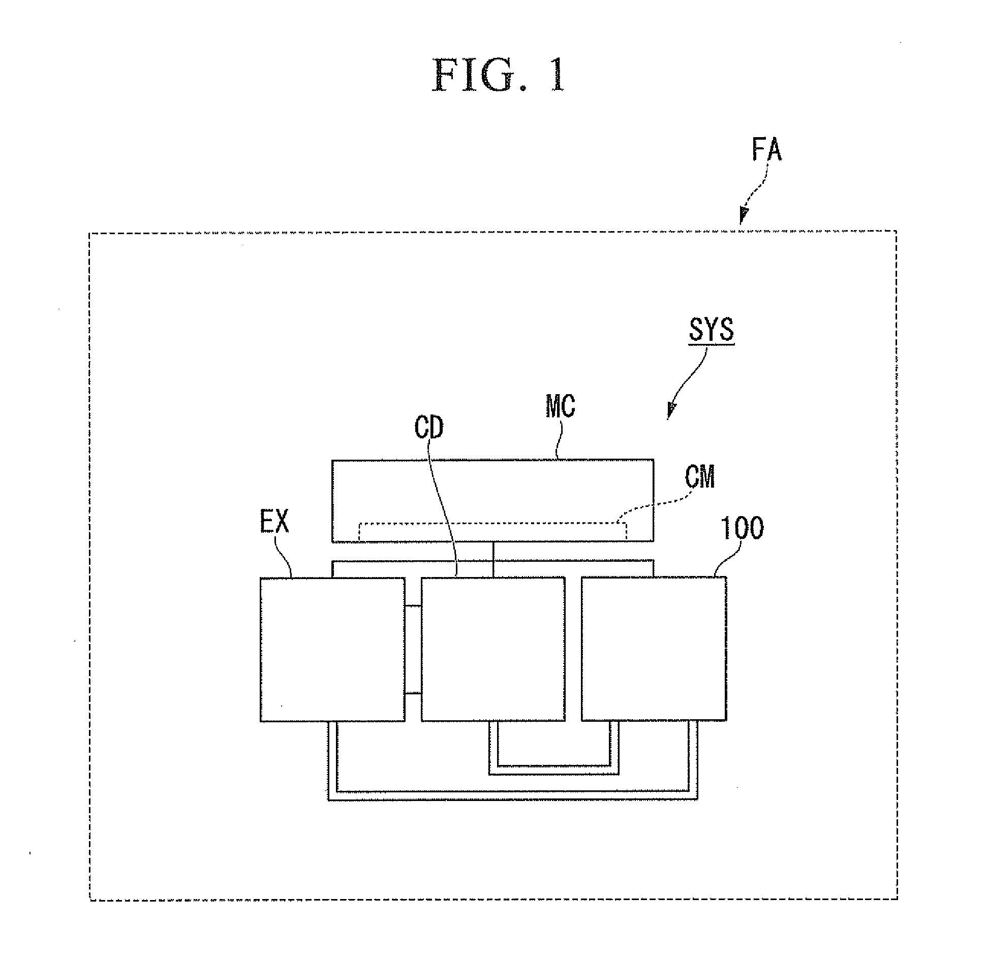
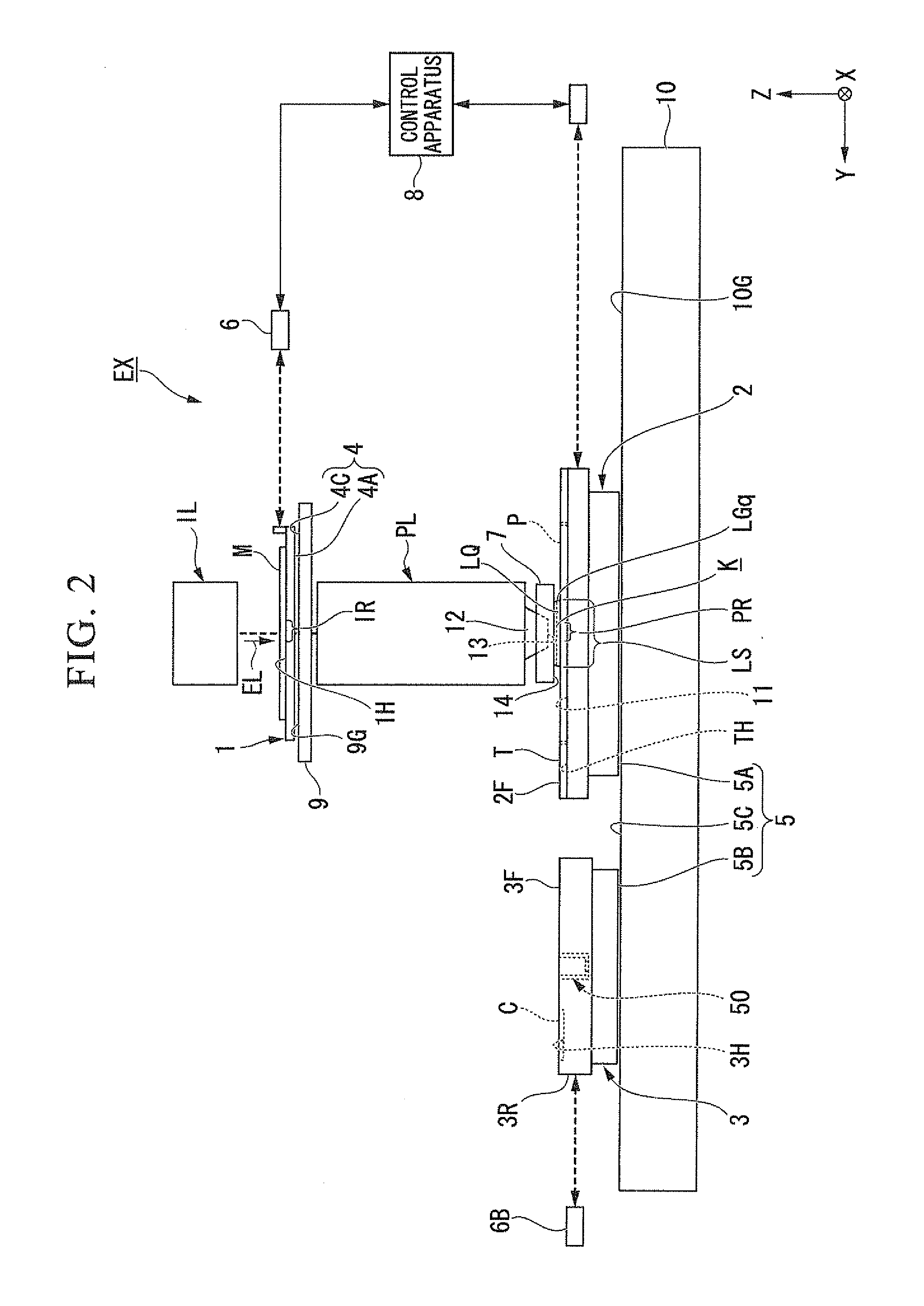
[0062]A first embodiment will be described. FIG. 1 is a schematic diagram illustrating an example of a device manufacturing system SYS according to a first embodiment. The device manufacturing system SYS includes a plurality of apparatuses. In the present embodiment, the device manufacturing system SYS includes an exposure apparatus EX that exposes a photosensitive substrate P with exposure light EL, a coater / developer apparatus CD including a film formation apparatus that forms a photosensitive film on the base material of the substrate P and a development apparatus that develops the substrate P after exposure, a liquid system 100 capable of supplying liquid used for manufacturing a device, a main controller MC that controls a plurality of these apparatuses, and a communication system CM capable of performing communication between a plurality of apparatuses. The communication system CM can perform communication of various types of information relating to the manufacture of a device...

second embodiment

[0307]Next, a second embodiment will be described. In the following description, the same reference signs and numerals are given to the same components as those of the above-mentioned embodiment, and a description thereof will be simplified or omitted here.

[0308]In the present embodiment, for example, in the second rinse process, until the concentration of the second cleaning liquid LC2 contained in the rinse liquid LH received in the third receiving member 43 becomes a predetermined concentration or less which does not influence the waste liquid process, the rinse liquid LH recovered from the recovery port 20 is continuously sent out to the third receiving member 43.

[0309]Since the rinse liquid LH recovered from the recovery port 20 is sent out to the third receiving member 43 during the supply of the rinse liquid LH from the first supply port 21 and the recovery thereof from the recovery port 20, the concentration of the second cleaning liquid LC2 contained in the rinse liquid LH ...

third embodiment

[0324]Next, a second embodiment will be described. In the following description, the same reference signs and numerals are given to the same components as those of the above-mentioned embodiment, and a description thereof will be simplified or omitted here.

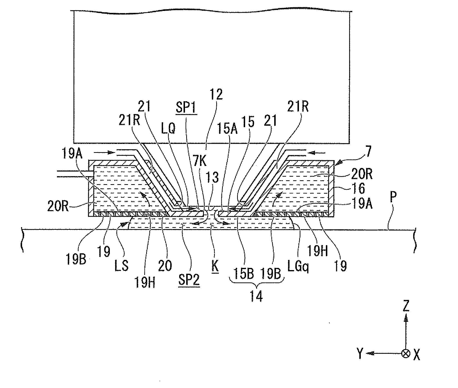
[0325]FIG. 18 is a side cross-sectional view illustrating an example of a cleaning apparatus 600 according to the second embodiment, and FIG. 19 is a plan view when the cleaning apparatus 600 is seen from the upper side. In the present embodiment, a case in which the liquid immersion member 7 is cleaned using the cleaning apparatus 600 capable of facing the liquid immersion member 7 will be described by way of example.

[0326]In FIGS. 18 and 19, the cleaning apparatus 600 includes a holding member 60 which is capable of holding the liquid (at least one of the first cleaning liquid LC1, the second cleaning liquid LC2, and the rinse liquid LH). The holding member 60 has a plate-shaped base member 61 and a sidewall member 62, connected...


PUM


Abstract

A cleaning method comprises: cleaning the liquid contact member by supplying a first liquid for cleaning to the liquid contact member; recovering the first liquid supplied to the liquid contact member; supplying a second liquid different from the first liquid to the liquid contact member after the liquid contact member is cleaned with the first liquid; recovering the second liquid supplied to the liquid contact member; and performing a process in which a concentration of the first liquid comprised in the recovered second liquid is set to a predetermined concentration or less.

Description

CROSS-REFERENCE TO RELATED APPLICATION[0001]This application is a non-provisional application claiming priority to and the benefit of U.S. provisional application Nos. 61 / 320,451, and 61 / 320,469, filed on Apr. 2, 2010, and U.S. Patent Application filed on Apr. 1, 2011. The entire contents of which are incorporated herein by reference.BACKGROUND[0002]1. Field of the Invention[0003]The present invention relates to a cleaning method, a device manufacturing method, an exposure apparatus, and a device manufacturing system.[0004]2. Description of Related Art[0005]In a process of manufacturing micro devices such as semiconductor devices and electronic devices, liquid immersion exposure apparatuses that expose a substrate with exposure light through exposure liquid are used. In liquid immersion exposure apparatuses, there is a possibility that a liquid contact member which is in contact with exposure liquid may be contaminated. For this reason, for example, as disclosed in U.S. Patent Appli...

Claims


Application Information

Patent Timeline
Patent Type & Authority Applications(United States)
IPC IPC(8): G03B27/52
CPCG03F7/70925G03F7/70341H01L21/0273
Inventor TANAKA, RYOKANAI, SUGURUSHIRAISHI, KENICHIWATANABE, SHUNJISHIBUYA, TAKASHI
Owner NIKON CORP
Why Eureka
Try Eureka