Drive control circuit for vibration speaker

a technology of drive control circuit and vibration speaker, which is applied in the direction of transducer details, power conversion systems, electrical transducers, etc., can solve the problems of vibration weakening and yield drop

Active Publication Date: 2012-03-15
SEMICON COMPONENTS IND LLC
View PDF5 Cites 12 Cited by
  • Summary
  • Abstract
  • Description
  • Claims
  • Application Information

AI Technical Summary

Benefits of technology

[0010]A drive control circuit of a vibration speaker according to one embodiment of the present invention includes a voice coil; a magnetic circuit that produces reciprocating motion within a certain prescribed range; and a vibration plate that vibrates by force generated by electricity flowing through the voice coil and magnetic field of the magnetic circuit, the vibration speaker having a speaker mode for generating sound by vibrating the vibration plate and a vibration mode for transmitting vibration of the magnetic circuit to another vibration member, and the drive control circuit includes: a drive signal generating unit configured to generate a drive signal, for use with the speaker mode, in response to an audio signal set externally in the speaker mode and configured to generate a drive signal, for use with the vibration mode, having a cyclic waveform containing a zero period in the vibration mode; a driver unit confi

Problems solved by technology

Thus, in the conventional method where a fixed drive frequency is set to all drive control circuits for the vibration speakers, there are drive control circuits with a significant disagreement between the eigen frequency of the vibration speaker and the driv

Method used


Image

  • Drive control circuit for vibration speaker
  • Drive control circuit for vibration speaker
  • Drive control circuit for vibration speaker

Examples


Embodiment Construction

[0020]The invention will now be described by reference to the preferred embodiments. This does not intend to limit the scope of the present invention, but to exemplify the invention.

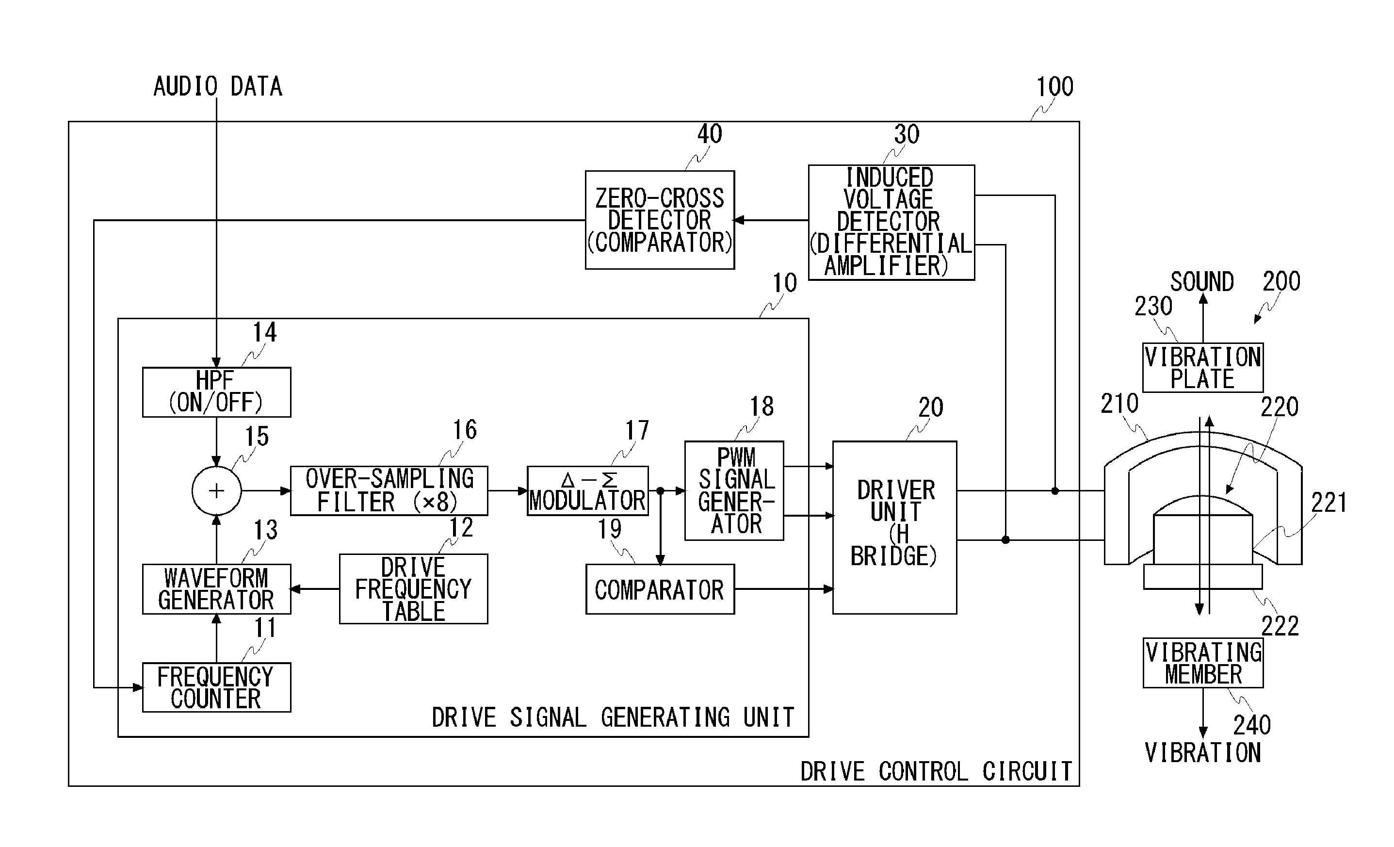
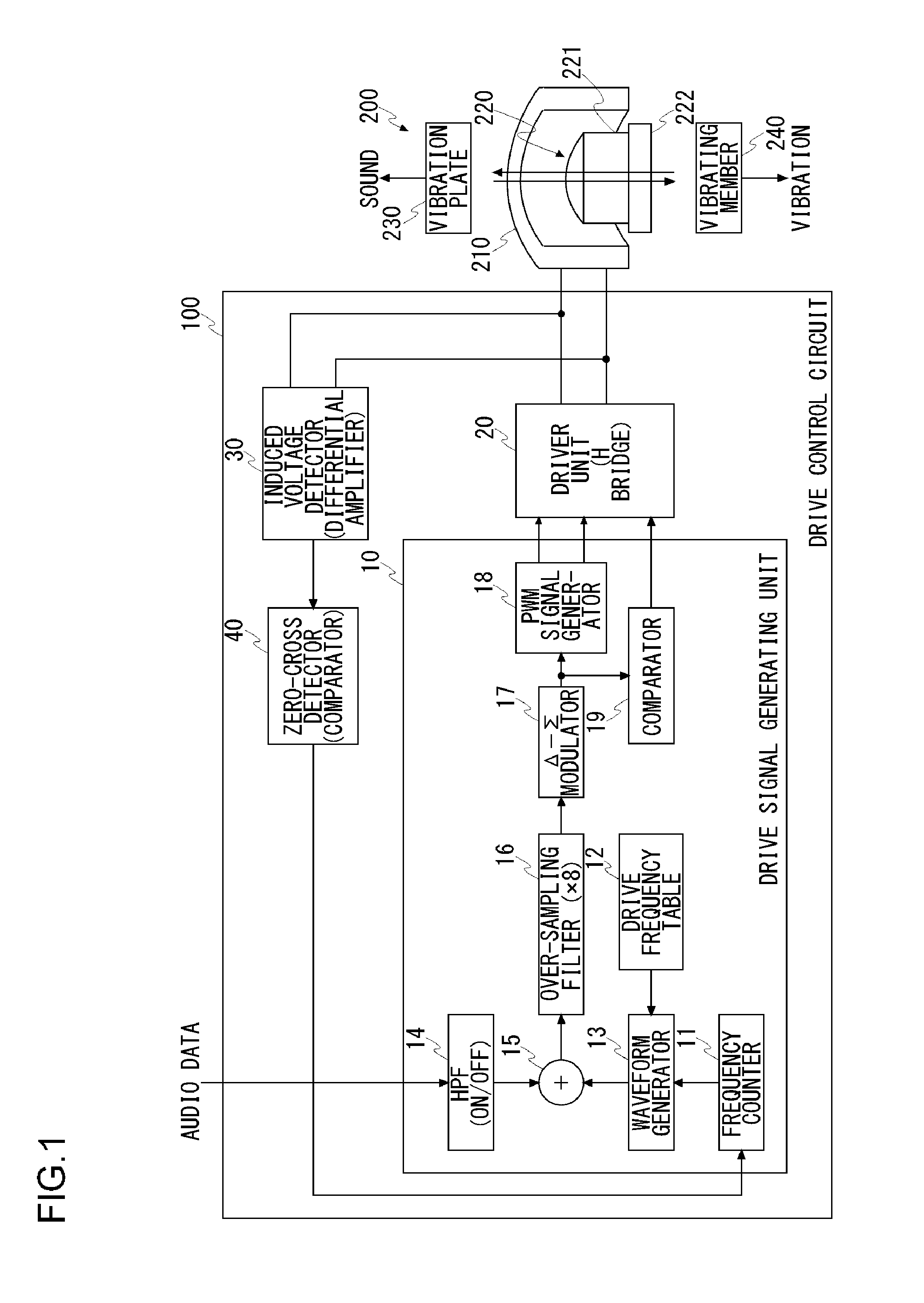
[0021]FIG. 1 shows a configuration of a drive control circuit 100 of a vibration speaker 200 according to an embodiment of the present invention. The vibration speaker 200 includes a voice coil 210, a magnetic circuit 220 that produces reciprocating motion within a certain prescribed range, and a vibration plate 230 (e.g., diaphragm) that vibrates by the force generated by the electricity flowing through the voice coil 210 and the magnetic field of the magnetic circuit 220.

[0022]The magnetic circuit 220 is configured such that a permanent magnet 221 is fixed on a base 222. The permanent magnet 221 is fixed on the base 222 so that the magnetic field is produced in the horizontal direction from the permanent magnet 221. Though not shown in FIG. 1, the magnetic circuit 220 may be configured such that the ma...


PUM


Abstract

A drive signal generating unit generates a drive signal having a cyclic waveform containing a zero period in a vibration mode. A driver unit generates the drive current in response to the drive signal generated by the drive signal generating unit so as to supply the drive current to a voice coil. An induced voltage detector detects the induced voltage occurring in the voice coil during a nonconducting period. A zero-cross detector detects the zero cross of the induced voltage detected by the induced voltage detector. The drive signal generating unit estimates the eigen-frequency of a vibration speaker from a detected position of the zero cross and brings the frequency of the drive signal close to the estimated eigen-frequency.

Description

[0001]This application is based upon and claims the benefit of priority from the prior Japanese Patent Application No. 2010-203111, filed on Sep. 10, 2010, the entire content of which is incorporated herein by reference.BACKGROUND OF THE INVENTION[0002]1. Field of the Invention[0003]The present invention relates to a drive control circuit of a vibration speaker having both a vibration function and a speaker function.[0004]2. Description of the Related Art[0005]A vibration speaker equipped with a vibration function and a speaker function is in practice use today. Since the vibration speaker is equipped with the both functions, it is expected that mobile devices (e.g., mobile phones, smartphones, portable game devices) into which the vibration speakers are incorporated be smaller in size and light in weight.[0006]The vibration speaker, which is basically of the same configuration as a dynamic speaker, is provided with a voice coil, a magnetic circuit, and diaphragm. The force produced...

Claims


Application Information

Patent Timeline
IPC IPC(8): H04R9/06
CPCH04R3/00H04R2400/01H04R9/10H04R9/025H02M7/5387H02P7/06
Inventor AOKI, DAISUKEMURATA, TSUTOMU
Owner SEMICON COMPONENTS IND LLC
Why Eureka
Try Eureka