Technique for Repairing a Reflective Photo-Mask

a reflective and photo-mask technology, applied in the field of photo-mask repair techniques, can solve the problems of difficult manufacturing of structure, difficult design and manufacture of transmission photo-masks at small wavelengths, and defects in multi-layer stacks

a reflective and photo-mask technology, applied in the field of photo-mask repair techniques, can solve the problems of difficult manufacturing of structure, difficult design and manufacture of transmission photo-masks at small wavelengths, and defects in multi-layer stacks

US20120066651A1Active Publication Date: 2012-03-15KLA TENCOR TECH CORP

Image

  • Technique for Repairing a Reflective Photo-Mask
  • Technique for Repairing a Reflective Photo-Mask
  • Technique for Repairing a Reflective Photo-Mask

Examples


Embodiment Construction

[0031]The following description is presented to enable any person skilled in the art to make and use the invention, and is provided in the context of a particular application and its requirements. Various modifications to the disclosed embodiments will be readily apparent to those skilled in the art, and the general principles defined herein may be applied to other embodiments and applications without departing from the spirit and scope of the present invention. Thus, the present invention is not intended to be limited to the embodiments shown, but is to be accorded the widest scope consistent with the principles and features disclosed herein.

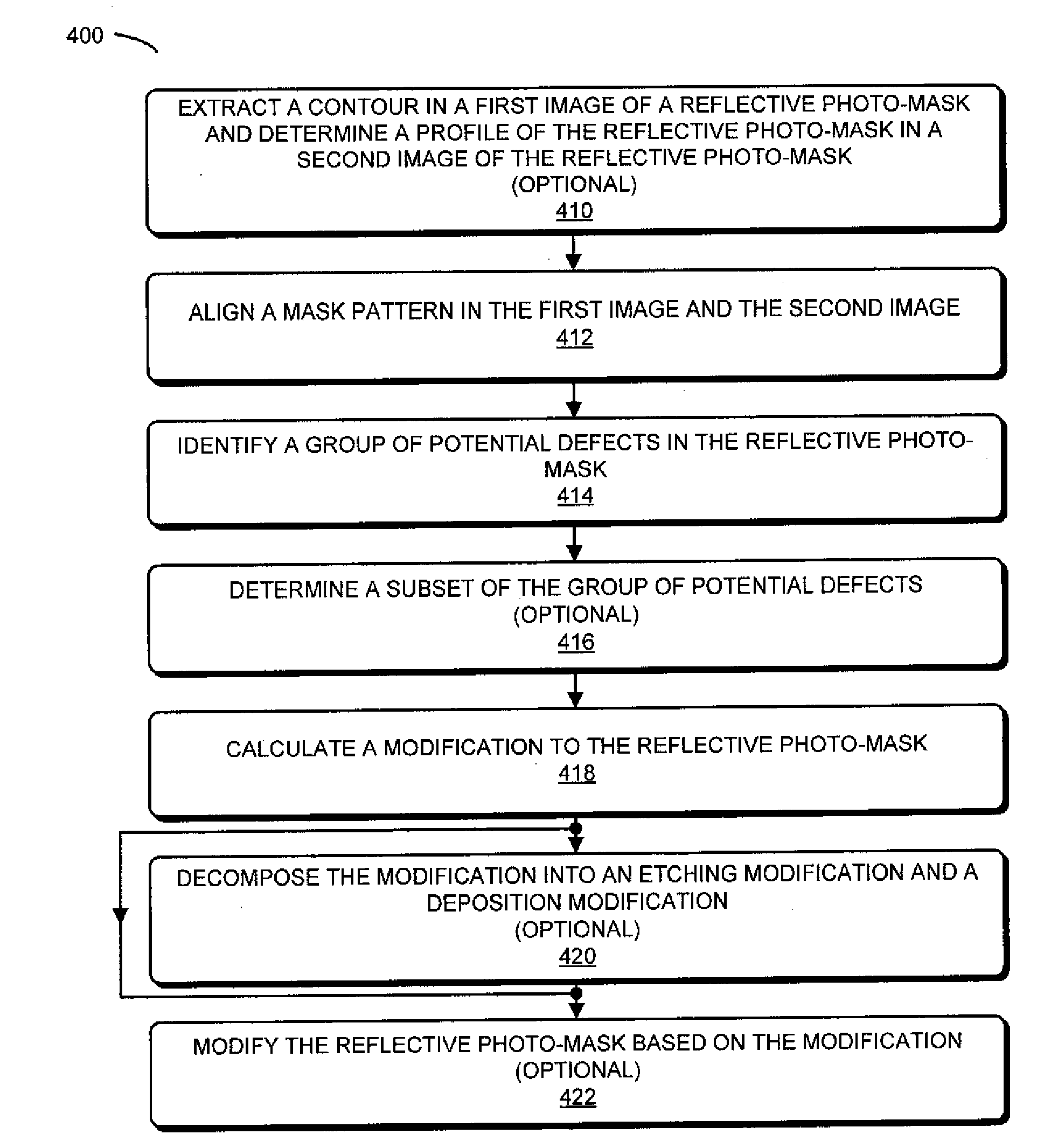
[0032]Embodiments of a computer system, a method, and a computer program product (i.e., software) for use with the computer system are described. These devices and processes may be used to calculate a modification to a reflective photo-mask, which, in turn, can be used to modify or repair one or more defects in the reflective photo-mask. In par...


PUM


Abstract

During a calculation technique, a modification to a reflective photo-mask is calculated. In particular, using information associated with different types of analysis techniques a group of one or more potential defects in the reflective photo-mask is determined. Then, the modification to the reflective photo-mask is calculated based on at least a subset of the group of potential defects using an inverse optical calculation. In particular, during the inverse optical calculation, a cost function at an image plane in a model of the photolithographic process is used to determine the modification to the reflective photo-mask at an object plane in the model of the photolithographic process.

Description

CROSS REFERENCE TO RELATED APPLICATIONS[0001]This application claims priority under 35 U.S.C. §120 to U.S. Non-provisional application Ser. No. 13 / 021,591 entitled “Technique for Analyzing a Reflective Photo-Mask,” by Christopher Heinz Clifford, filed on Feb. 4, 2011, and claims the benefit of U.S. Provisional Application Ser. No. 61 / 382,857 entitled “Technique for Analyzing a Reflective Photo-Mask,” by Christopher Heinz Clifford, each of which are herein incorporated by reference.BACKGROUND OF THE INVENTION[0002]1. Field of the Invention[0003]The present invention relates to techniques for repairing a photo-mask. More specifically, the invention relates to a technique for calculating a modification to a reflective photo-mask, which is to be used in a photolithographic process.[0004]2. Related Art[0005]Photolithography is a widely used technology for producing integrated circuits. In this technique, a light source illuminates a photo-mask. The resulting spatially varying light patte...

Claims


Application Information

Patent Timeline
15 Mar 2012
Publication
US20120066651A1
IPC
G06F17/50
CPC
G03F1/70; G03F1/00
Inventors
PANG, LINYONG; CLIFFORD, CHRISTOPHER HEINZ