Support for an upright structure

a technology for supporting structures and upright structures, applied in the direction of machine supports, other domestic objects, mechanical apparatus, etc., can solve the problems of time-consuming and expensive prior provision of super structures, requiring a modest amount of expensive materials, and not being well suited to remote areas and places. , to achieve the effect of less expensiv

Inactive Publication Date: 2012-03-22
ERICH RICHARD +1
View PDF6 Cites 15 Cited by
  • Summary
  • Abstract
  • Description
  • Claims
  • Application Information

AI Technical Summary

Benefits of technology

[0016]A further object of the present invention is to provide a foundation apparatus for supporting an uprigh

Problems solved by technology

Unfortunately, the prior provision of foundations for super structures have been proved to be time consuming and expensive.
In addition, such a system of supporting super structures is not well suited to remote areas and places of uneven or roc

Method used


Image

  • Support for an upright structure
  • Support for an upright structure
  • Support for an upright structure

Examples


Embodiment Construction

[0026]Various aspects of the present invention will evolve from the following detailed description of the preferred embodiments thereof which should be referenced to the prior described drawings.

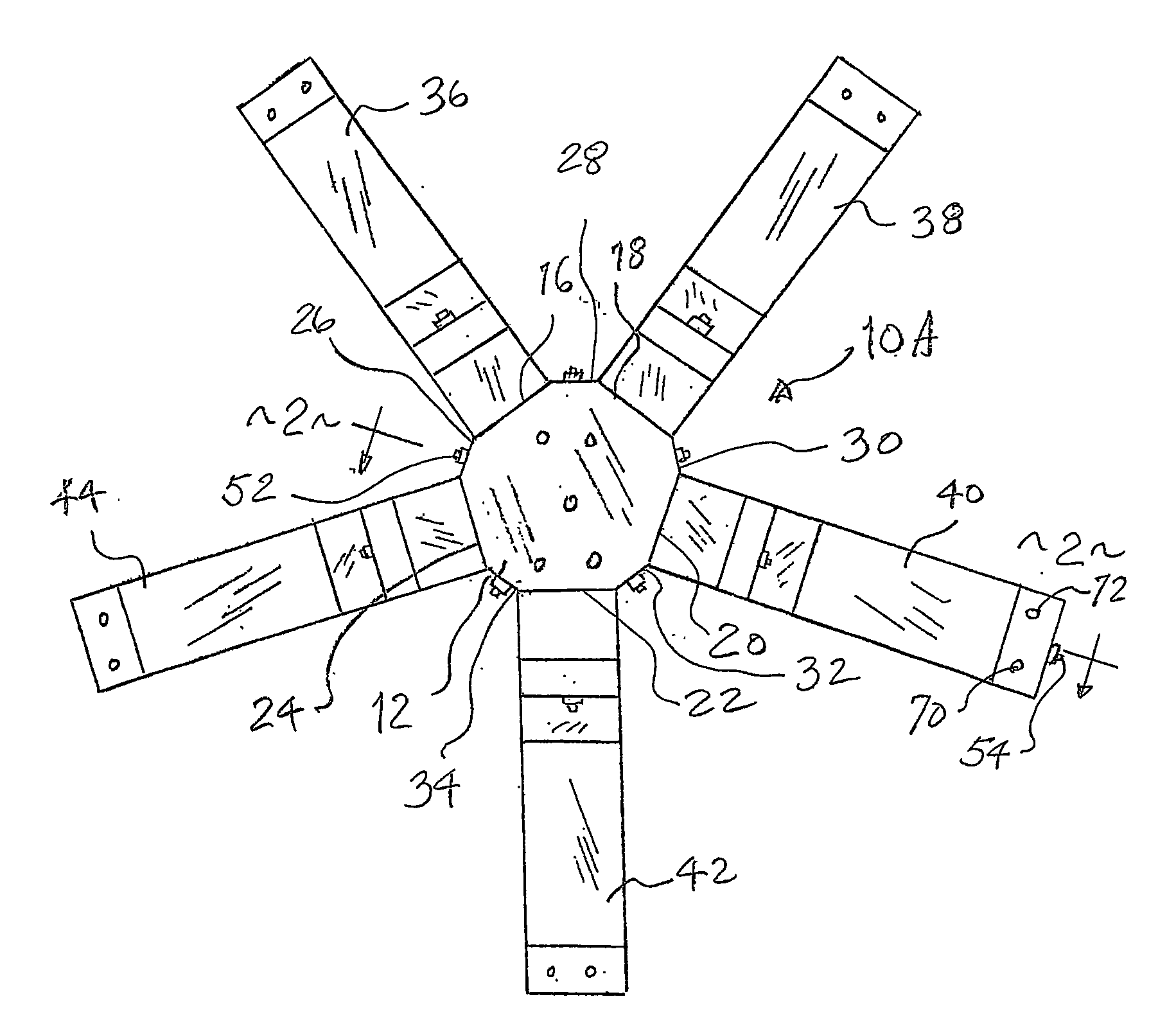
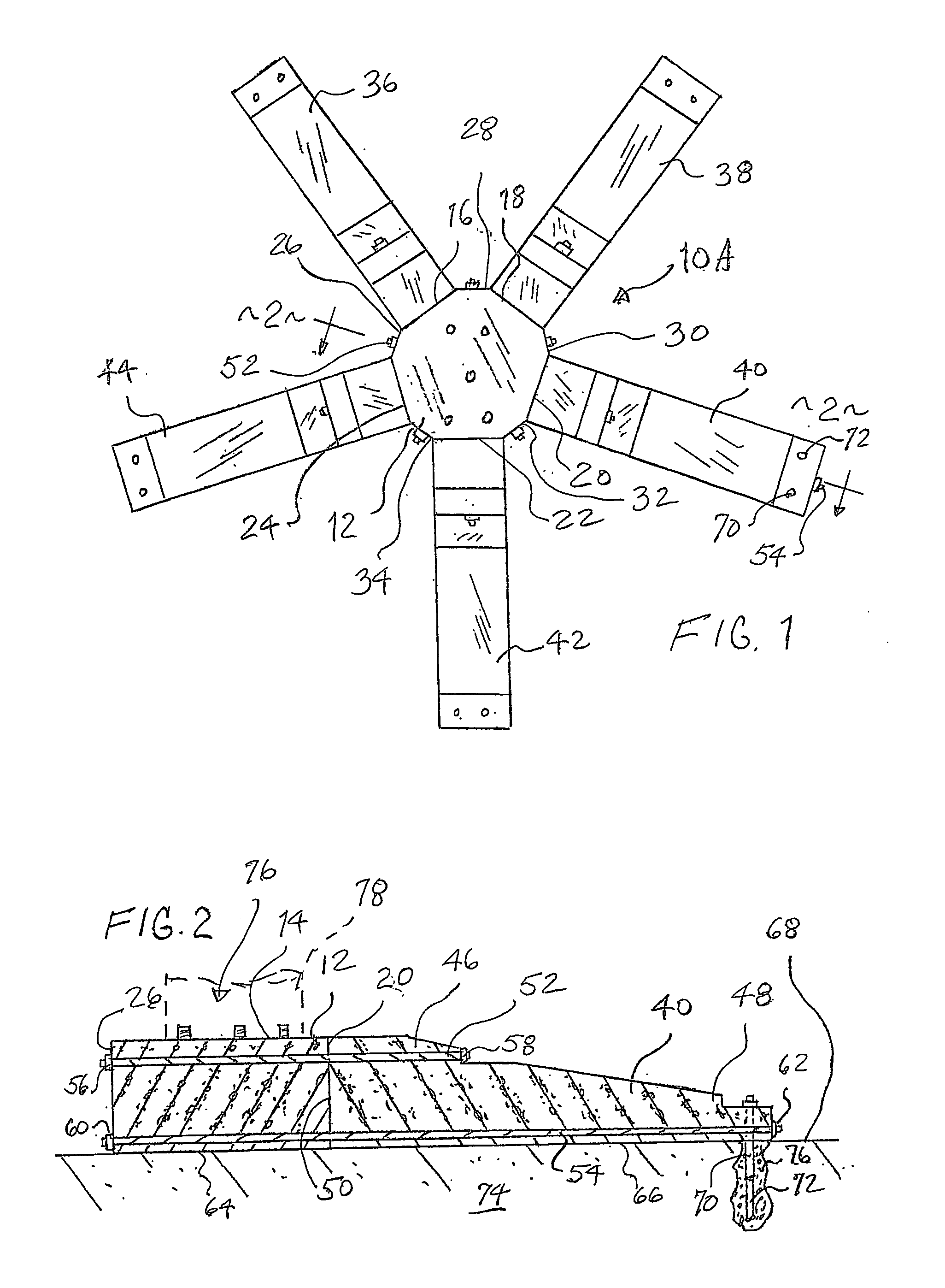
[0027]An embodiment of the invention as a whole is shown in the drawings by reference character 10 followed by an upper case letter to denote variations of the same. With reference to FIG. 1, it may be observed that structure 10A is shown. Structure 10A includes as one of its elements, block 12 which is formed of concrete or similar material. Block 12 is constructed as a faceted member having a top surface 14 and five long flattened surfaces 16, 18, 20, 22, and 24. Short flattened side surfaces 26, 28, 30, 32, and 34 lie between pairs of surfaces 16, 18, 20, 22, and 24. It should be noted that surfaces 26, 28, 30, 32, and 34 are laterally shorter than side surfaces 16, 18, 20, 22, and 24. For example, short side surface 26 lies between long side surfaces 16 and 24.

[0028]As depicted in FIG. 1...


PUM


Abstract

A system for supporting a super structure utilizing a plurality of blocks that are connected laterally to one another through tensioning elements. The super structure is supported to at least one of the blocks which are positioned on or near a ground surface. A plurality of piles extend through the blocks to anchor the same beneath the soil and aid in the support of the super structure.

Description

BACKGROUND OF THE INVENTION[0001]The present invention relates to a novel and useful upright structure support apparatus.[0002]Towers and antennas are widely used in communication facilities to transmit and receive signals over long distances. Such towers and antennas must be supported above a ground surface to allow the tower or antenna to extend a requisite distance in order to be effective. In the past, foundations have been employed to support such towers and antennas by providing a geological assessment, excavating soil, and employing a subterranean foundation according to an engineering plan. Unfortunately, the prior provision of foundations for super structures have been proved to be time consuming and expensive. In addition, such a system of supporting super structures is not well suited to remote areas and places of uneven or rocky terrain.[0003]In the past, a novel system was proposed by U.S. Pat. No. 6,050,038 in which a plurality of blocks were connected to one another b...

Claims


Application Information

Patent Timeline
IPC IPC(8): F16M11/22
CPCE02D27/00H01Q1/1242E04H12/2238
Inventor ERICH, RICHARDFEY, JAMES
Owner ERICH RICHARD
Why Eureka
Try Eureka