Vehicle Wheel Suspension of the Semi-Trailer Type

Active Publication Date: 2012-03-22
BAYERISCHE MOTOREN WERKE AG
View PDF9 Cites 9 Cited by
  • Summary
  • Abstract
  • Description
  • Claims
  • Application Information

AI Technical Summary

Benefits of technology

[0008]Both the support arm proposed herein and the second trailing arm can be designed in a simple way so that they can permanently absorb the forces that are to be transmitted and that predominantly involve the lateral forces acting on the wheel. The same applies to the bearings or joints, by which the second trailing arm is ultimately connected to the vehicle chassis. Similarly, the wheel carrier with the first trailing arm can be easily designed so that it satisfies all of the requirements without having to pay particular attention to the desired pivot motion in the toe-in direction when designing the wheel carrier, for example, with respect to stability. In other words, the engineering object is achieved by using, instead of the past conventional simple semi-trailer, a semi-trailer that is formed from two components that can be slight

Problems solved by technology

The person skilled in the art knows that simple semi-trailer type wheel suspensions, which are used preferably at the driven rear axles of motor vehicles, have an undesired oversteer tendency in that the wheel that is on

Method used


Image

  • Vehicle Wheel Suspension of the Semi-Trailer Type
  • Vehicle Wheel Suspension of the Semi-Trailer Type
  • Vehicle Wheel Suspension of the Semi-Trailer Type

Examples


Example

DETAILED DESCRIPTION OF THE DRAWINGS

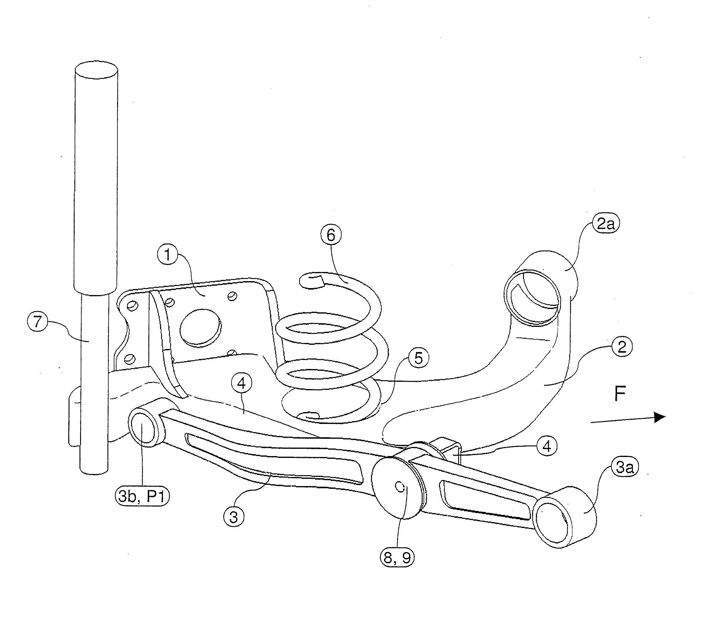
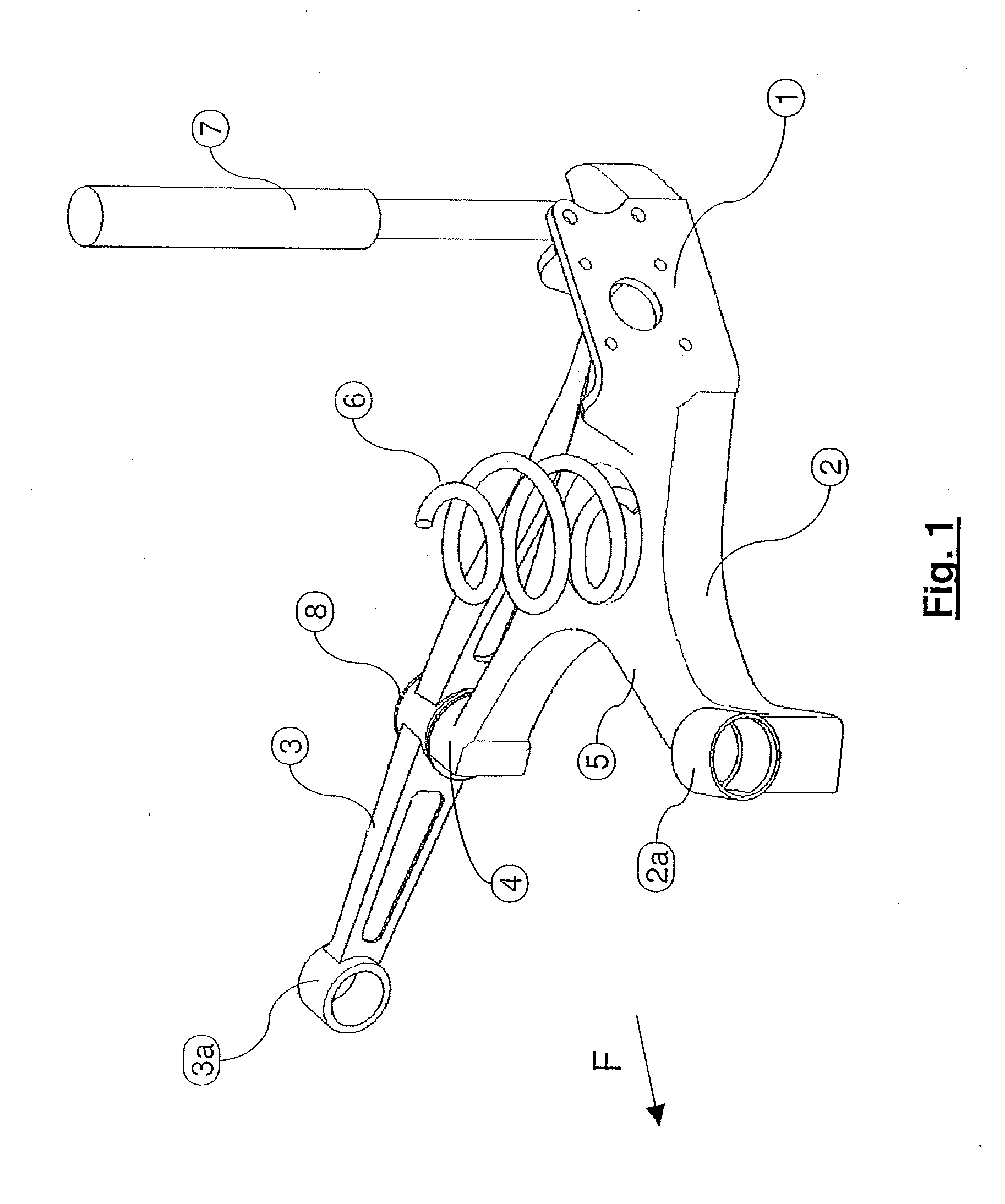
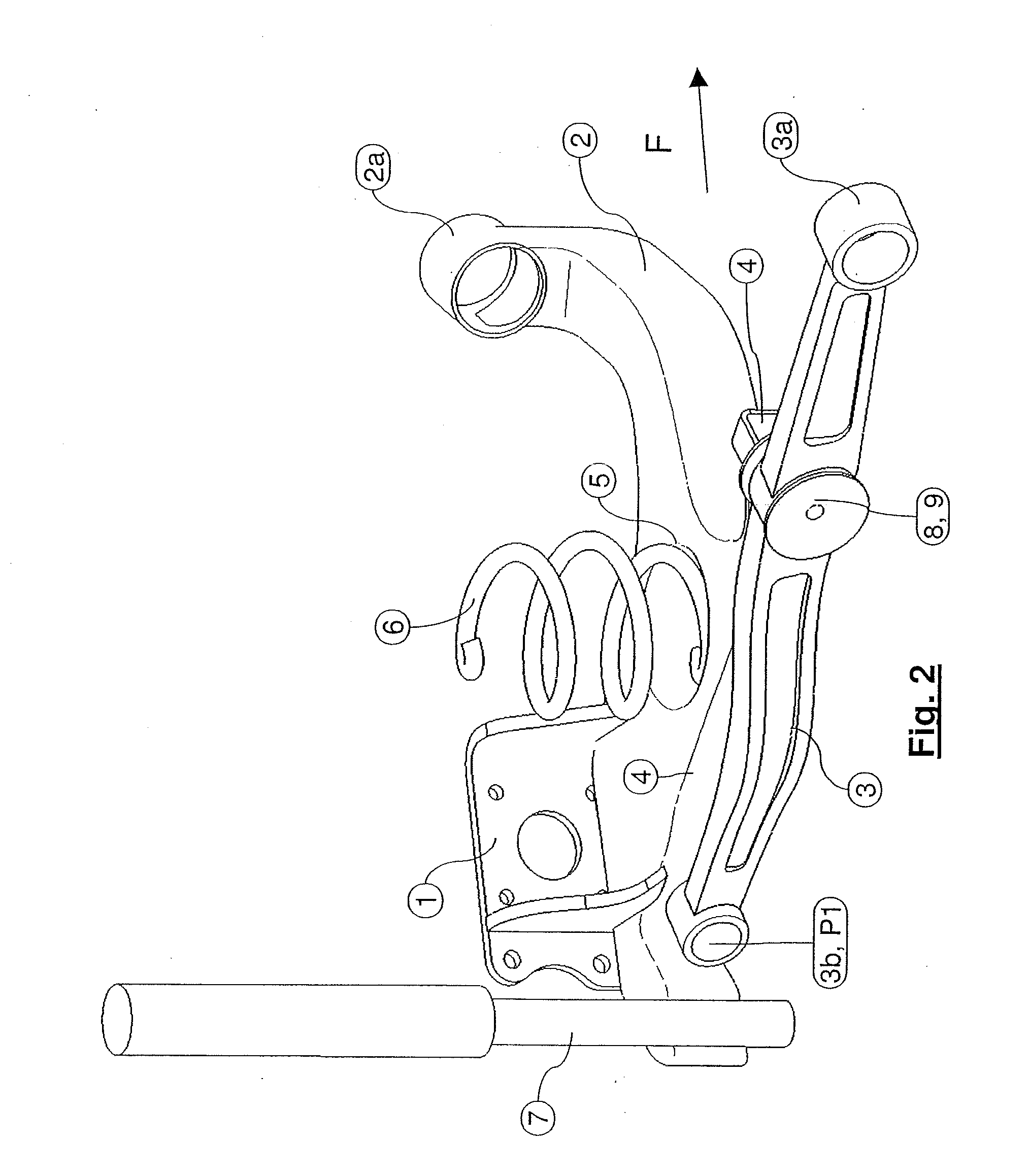
[0021]A left rear wheel suspension of a passenger vehicle is shown as an exemplary embodiment of the invention in figures. In all of the figures, identical components are marked with the same reference numerals.

[0022]In this context a wheel carrier, on which a wheel (not illustrated) is mounted in a rotatable manner about its axis of rotation, bears the reference numeral 1. A first trailing arm 2 is provided in one piece on this wheel carrier 1. Extending from the wheel carrier 1, this first trailing arm is oriented towards the front essentially in the longitudinal direction of the vehicle (or more specifically the direction of travel F). A second trailing arm 3 is connected in an articulated manner to the wheel carrier 1 at a point P1 that is located on the wheel carrier 1 relatively near the wheel. This second trailing arm 3 extends from the wheel carrier 1 essentially in the direction of an angle bisector between the longitudinal direction (F) ...


PUM


Abstract

In a vehicle wheel suspension, a first trailing arm is oriented in the longitudinal direction of the vehicle and a second trailing arm in the direction of an angle bisector between the longitudinal and transverse directions. The ends of the trailing arms determine a substantially horizontal instantaneous axis for the wheel carrier relative to the spring jounce and rebound motions of the vehicle chassis. The wheel carrier is slightly pivotable about a toe axis under the influence of braking forces. A support arm securely connects to the wheel carrier and extends over a defined distance substantially in parallel with and supported on the second trailing arm. The support is softer in the horizontal direction than in the vertical direction. A suitable design of the second trailing arm and/or the support arm allows a slight pivot motion of the wheel carrier about the toe axis.

Description

CROSS-REFERENCE TO RELATED APPLICATIONS[0001]This application is a continuation of PCT International Application No. PCT / EP2010 / 001921, filed Mar. 26, 2010, which claims priority under 35 U.S.C. §119 from German Patent Application No. DE 10 1009 021 672.3, filed May 16, 2009, the entire disclosures of which are herein expressly incorporated by reference.BACKGROUND AND SUMMARY OF THE INVENTION[0002]The invention relates to a vehicle wheel suspension of the semi-trailer type with trailing arms, which extend from a wheel carrier. A first trailing arm is oriented approximately in the longitudinal direction of the vehicle, and a second trailing arm extends approximately in the direction of an angle bisector between the longitudinal direction of the vehicle and the transverse direction of the vehicle. The ends of the trailing arms that are supported on the vehicle chassis by means of trailing arm bearings determine a substantially horizontal instantaneous axis for the wheel carrier relati...

Claims


Application Information

Patent Timeline
IPC IPC(8): B60G3/14
CPCB60G3/145B60G3/225B60G7/02B60G7/04B60G2204/421B60G2200/141B60G2200/18B60G2200/462B60G2200/1322
Inventor JAKOB, BENJAMIN
Owner BAYERISCHE MOTOREN WERKE AG
Why Eureka
Try Eureka