

oscillator
a technology of oscillator and oscillator, which is applied in the direction of oscillator generator, electrical apparatus, etc., can solve the problems that the oscillator cannot follow the ultrahigh-speed modulation, and the negative differential resistance element cannot be modulated at ultrahigh speed
- Summary
- Abstract
- Description
- Claims
- Application Information
AI Technical Summary
Benefits of technology
Problems solved by technology
Method used
Image

Examples
first embodiment
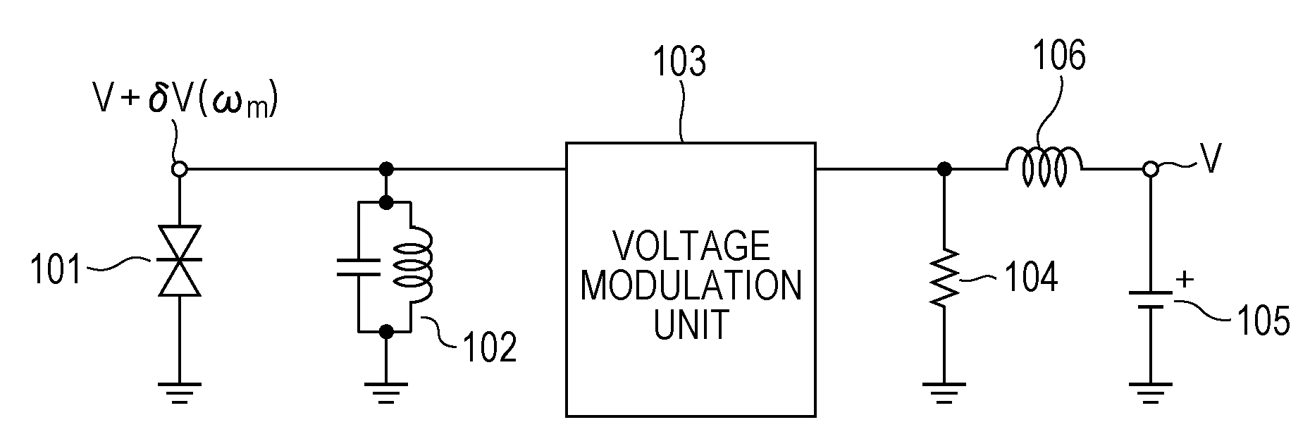
[0030]An oscillator according to a first embodiment will be described with reference to FIG. 1. FIG. 1 is a diagram illustrating a circuit configuration of the oscillator according to this embodiment.
[0031]The oscillator of this embodiment which includes a negative differential resistance element 101 and a resonator 102 which prescribes oscillation frequencies of electromagnetic waves oscillates electromagnetic waves in a frequency band in a range from a millimeter waveband to a terahertz waveband (equal to or larger than 30 GHz and equal to or smaller than 30 THz). The arrangement relationship between the negative differential resistance element 101 and the resonator 102 shown in FIG. 1 may be employed, and alternatively, the arrangement relationship in which positions of the negative differential resistance element 101 and the resonator 102 are replaced by each other may be employed. Furthermore, an inductance and a capacitance of the resonator 102 include an inductance component ...
second embodiment
[0035]An electromagnetic wave generation element according to a second embodiment will be described with reference to FIG. 3. FIG. 3 is a diagram illustrating a circuit configuration of an oscillator of this embodiment serving as a modification of the first embodiment.
[0036]This embodiment is specifically different from the first embodiment in that the voltage modulation unit 103 is configured by a resonator 203 having a modulation frequency of ωm. Other configurations are the same as those of the first embodiment. That is, the oscillator includes a negative differential resistance element 201, a resonator 202 having an oscillation frequency of ω0, a stabilizing circuit including a resistor 204, and a bias circuit including a power source 205 and a line 106. A resonator 203 having a modulation frequency of ωm may be a distributed constant resonator. In this case, the negative differential resistance element 201 oscillates the oscillation frequency ω0 of the first resonator 202 and t...
third embodiment
[0040]An electromagnetic wave generation element according to a third embodiment will be described with reference to FIG. 5. FIG. 5 is a diagram illustrating a circuit configuration of an oscillator of this embodiment serving as a modification of the first embodiment.
[0041]This embodiment is specifically different from the first embodiment in that the voltage modulation unit 103 is configured by photocoupler which transmit and receive a modulation frequency ωm. Use of the photocoupler enables a voltage modulation unit to be electrically isolated and a modulation frequency to be variable. Other configurations are the same as those of the first embodiment. That is, the oscillator includes a negative differential resistance element 501, a resonator 502 having an oscillation frequency of ω0, a stabilizing circuit (resistor) 504, and a bias circuit including a power source 505 and an inductance 506. Since a transmission optical element 5032 and a reception optical element 5031 are electr...
PUM
 Abstract
Description
Claims
Application Information