
System and method for determining the location of wireless sensors

a wireless sensor and location technology, applied in the field of wireless devices, can solve the problems of substantial time and money wasted attempting to find each particular wireless sensor, forgetting the exact location of each wireless sensor, and difficulty in obtaining

Active Publication Date: 2012-03-22
BAKER HUGHES INC
View PDF7 Cites 45 Cited by
  • Summary
  • Abstract
  • Description
  • Claims
  • Application Information

AI Technical Summary

Problems solved by technology

However, once installed within an industrial facility, it is often the case that the exact location of each wireless sensor is forgotten, misplaced and / or difficult to obtain.
As such, when one or more of the wireless sensors need to be serviced or otherwise located, a substantial amount of time and money can be wasted attempting to find each particular wireless sensor.

Method used


Image

  • System and method for determining the location of wireless sensors
  • System and method for determining the location of wireless sensors
  • System and method for determining the location of wireless sensors

Examples


Embodiment Construction

[0014]Reference now will be made in detail to embodiments of the invention, one or more examples of which are illustrated in the drawings. Each example is provided by way of explanation of the invention, not limitation of the invention. In fact, it will be apparent to those skilled in the art that various modifications and variations can be made in the present invention without departing from the scope or spirit of the invention. For instance, features illustrated or described as part of one embodiment can be used with another embodiment to yield a still further embodiment. Thus, it is intended that the present invention covers such modifications and variations as come within the scope of the appended claims and their equivalents.

[0015]The present subject matter generally provides a system for determining the location of wireless devices, such as wireless sensors. For example, in one embodiment, the system may be configured to locate wireless sensors dispersed throughout an industri...


PUM


Abstract

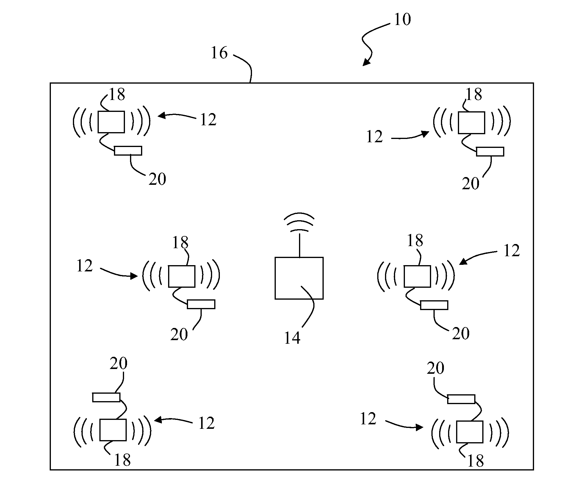
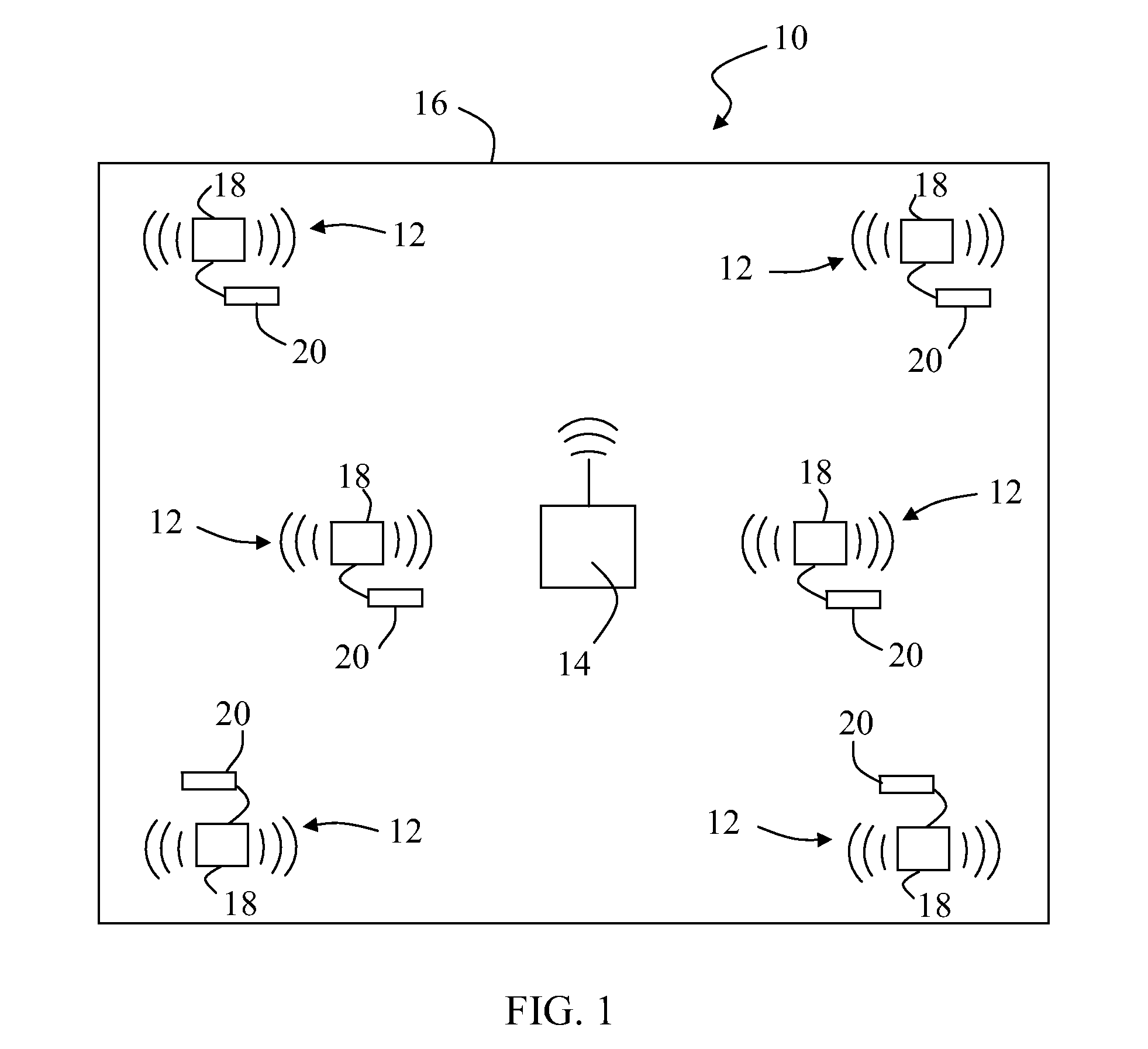
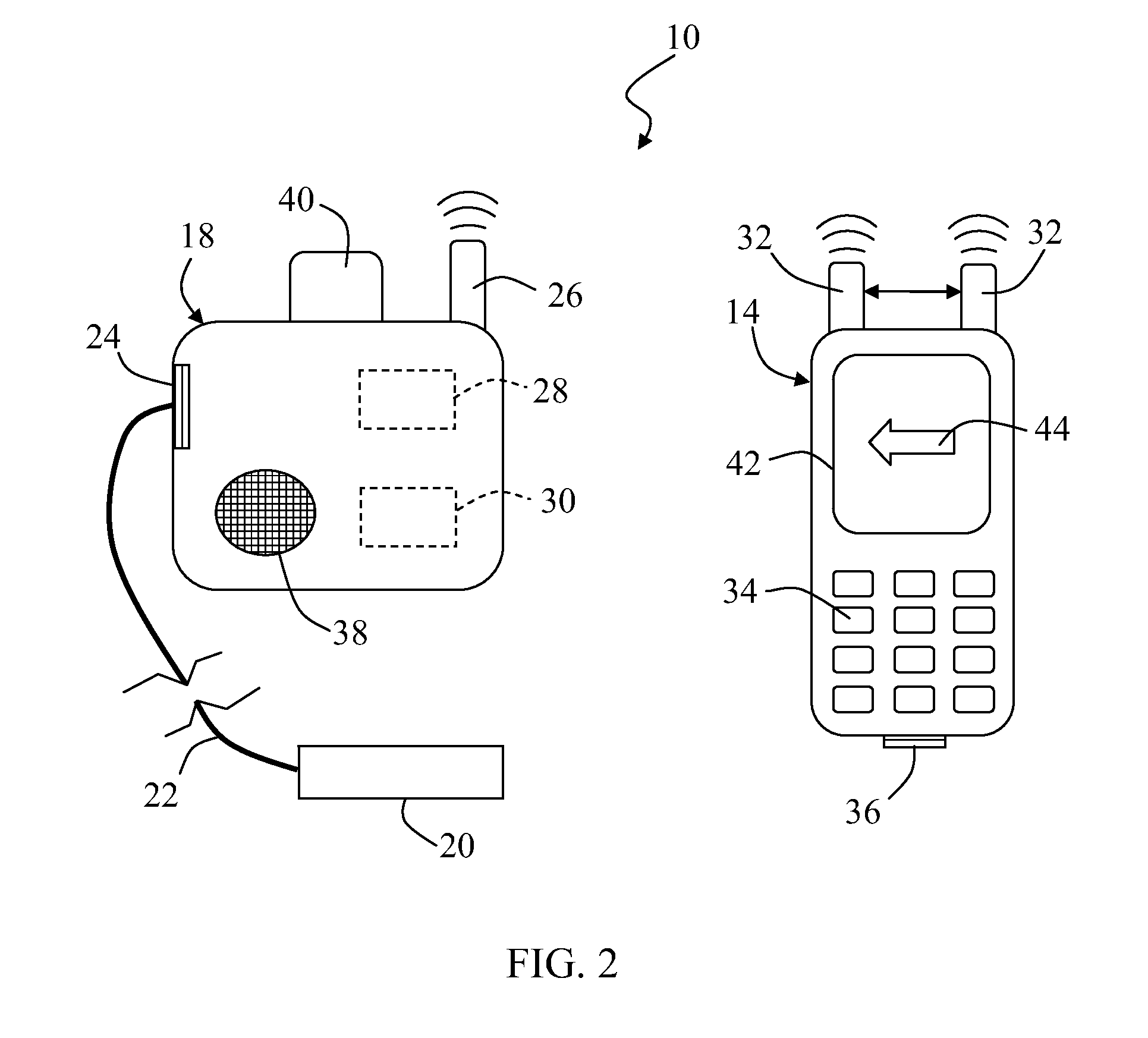
A system and method for determining the location of wireless sensors are disclosed. The system may generally include a plurality of wireless sensor nodes communicatively coupled to a plurality of sensing devices. Additionally, the system may include a paging device configured to wirelessly transmit a page command to at least one of the wireless sensor nodes. Further, the at least one wireless sensor node may be configured to produce a position indicator upon receipt of the page command.

Description

FIELD OF THE INVENTION[0001]The present subject matter relates generally to wireless devices and, more particularly, to a system and method for locating wireless sensors.BACKGROUND OF THE INVENTION[0002]Devices, such as probes, sensors transducers, cameras and the like, are used across a wide range of industries to monitor the operating conditions of industrial assets. For example, an industrial facility may include any number of essential assets, such as various types of machinery, and a plurality of supporting assets, such as pumps, motors, blowers, heat exchangers, fans and similar assets, that impact the process flowing through the essential assets. Such essential and / or supporting assets are often communicatively coupled to a variety of different devices to measure and / or sense the vibration, temperature, pressure, relative position and other operating parameters of the assets to ensure their proper operation and to appropriately schedule maintenance work.[0003]To decrease the ...

Claims


Application Information

Patent Timeline
Patent Type & Authority Applications(United States)
IPC IPC(8): H04Q1/30H04W4/02H04W4/38
CPCG01S5/00G01S5/0054G01S5/0226G01S5/12H04W84/18H04W4/02H04W64/00H04W68/00H04W4/006H04W4/38B60R22/48G08B5/38H04Q9/00
Inventor SHEIKMAN, BORIS LEONIDJENSEN, RAYMOND VERLE
Owner BAKER HUGHES INC
Learn More