

Moving image processing device and moving image processing method
a technology of moving image and processing device, which is applied in the field of moving image processing device and moving image processing method, can solve the problems of video that does not meet the standard, video that is not properly delivered or displayed, and may lose compatibility in the futur
- Summary
- Abstract
- Description
- Claims
- Application Information
AI Technical Summary
Problems solved by technology
Method used
Image

Examples
first embodiment
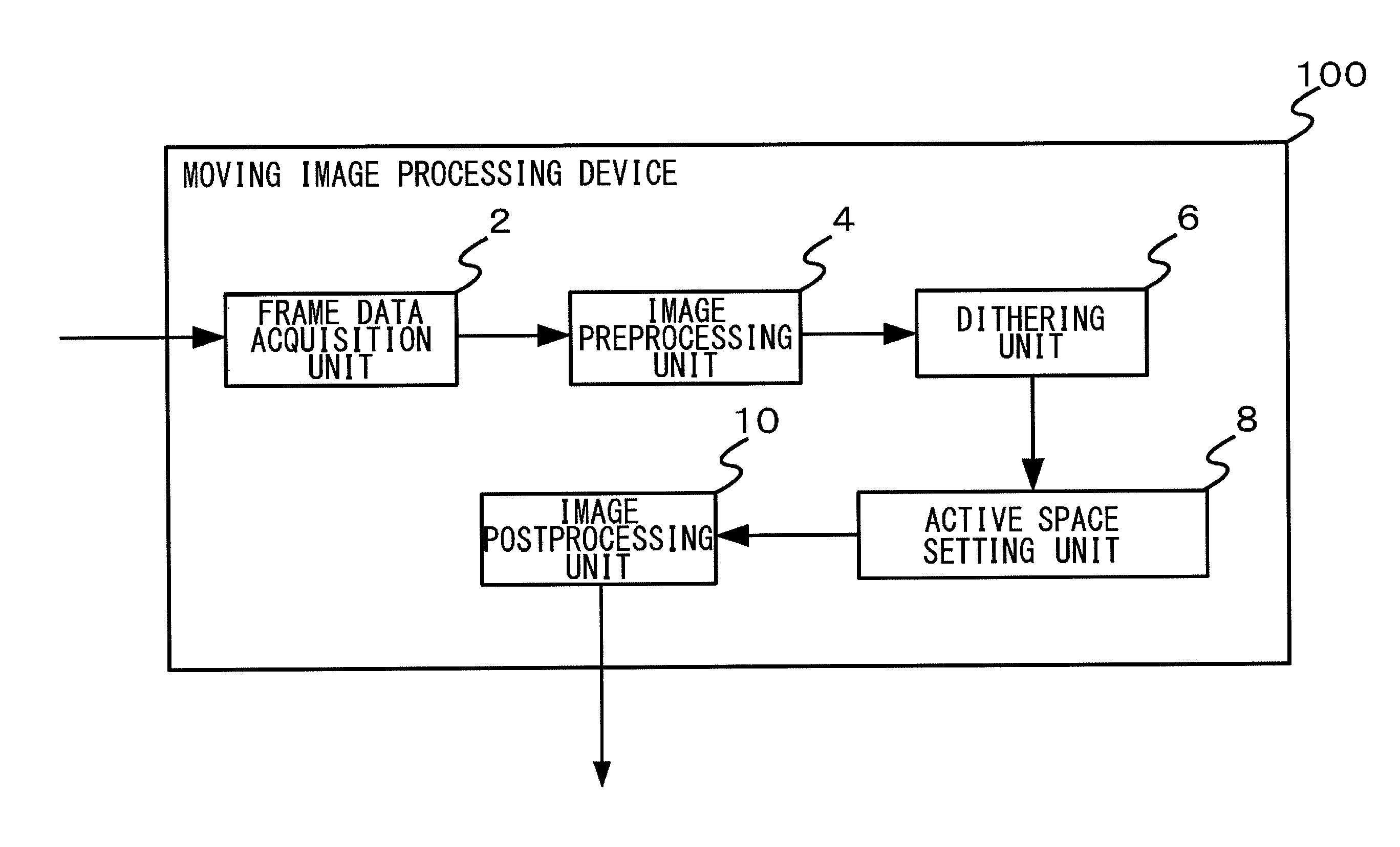
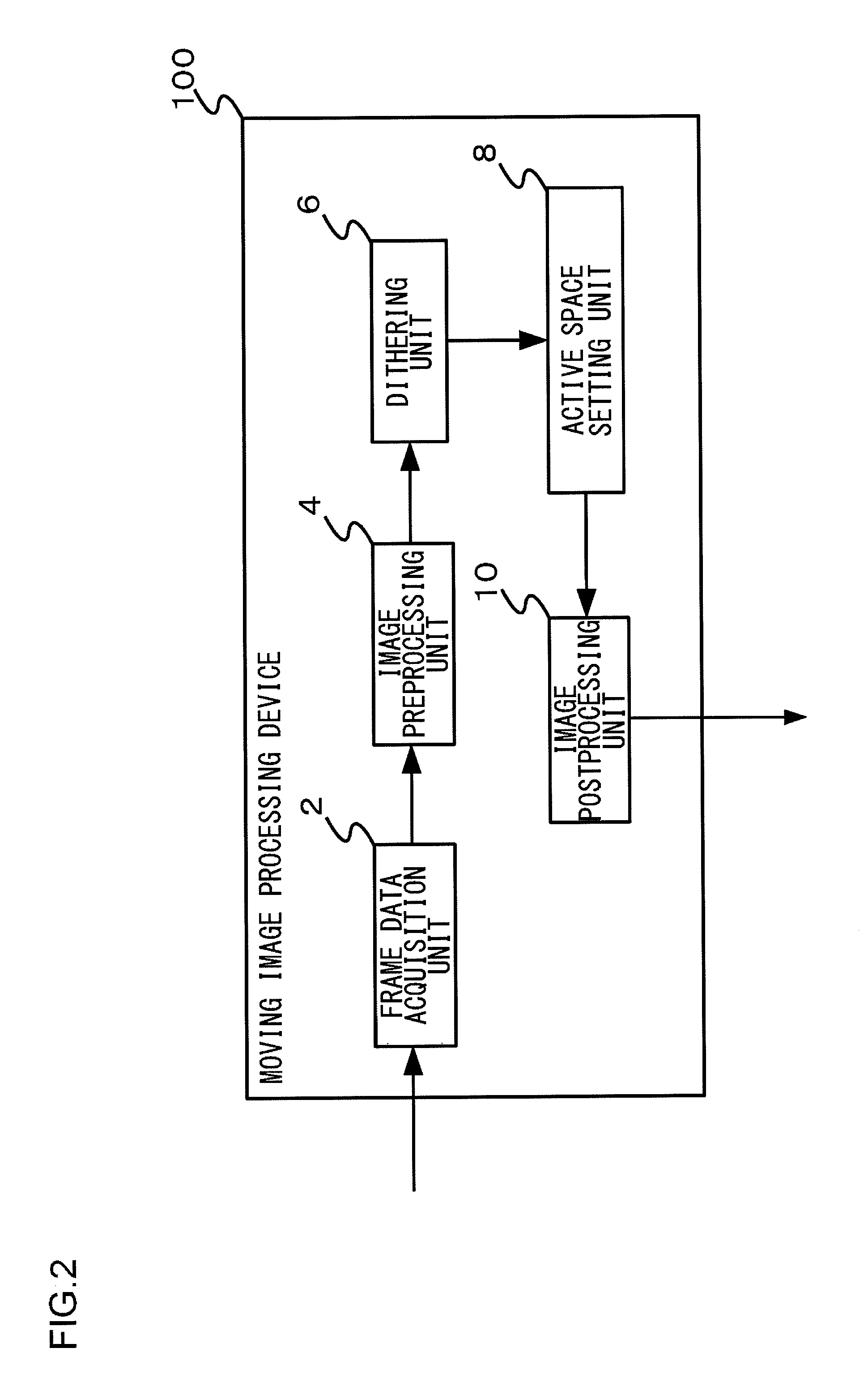
[0024]A summary of the first embodiment will be given. A moving image processing device 100 according to the first embodiment acquires frame data in which a parallax image for the left eye and a parallax image for the right eye are arranged across an active space. The moving image processing device 100 identifies the position of an active space within the frame data and sets the pixel values of the active space at predetermined fixed values. For identification of the position of the active space, the moving image processing uses a coordinate system using a vertical synchronization signal and a horizontal synchronization signal as references.
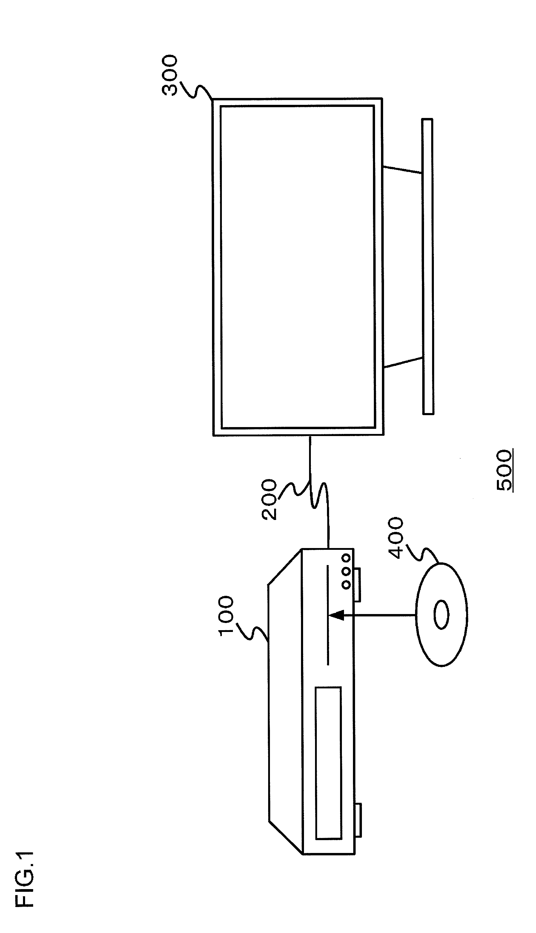
[0025]FIG. 1 schematically shows a moving image playback system 500 according to the first embodiment. The moving image playback system 500 includes a moving image processing device 100 and a display device 300.
[0026]For example, the moving image processing device 100 processes moving images stored in a recording medium such as a Blu-ray disk (re...
second embodiment
[0061]A description will now be given of the second embodiment. Like the moving image processing device 100 according to the first embodiment, the moving image processing device 100 according to the second embodiment acquires frame data in which a parallax image for the left eye and a parallax image for the right eye are arranged across an active space. The moving image processing device 100 identifies the position of an active space within the frame data and sets the pixel values of the active space at predetermined fixed values. The difference from the first embodiment is that the second embodiment identifies the position of an active space by using a data enable signal (hereinafter, referred to as “DE”) indicating that the pixels of the frame data are input. Hereinafter, the description that is a repetition from the first embodiment will be omitted or simplified.
[0062]FIG. 10 shows the principle of identifying the position of an active space according to the second embodiment.
[00...
third embodiment
[0067]A summary of the third embodiment will be given. Like the moving image processing device 100 according to the first and second embodiments, the moving image processing device 100 according to the third embodiment acquires frame data in which a parallax image for the left eye and a parallax image for the right eye are arranged across an active space. The moving image processing device 100 identifies the position of an active space within the frame data and sets the pixel values of the active space at predetermined fixed values. The third embodiment differs from the first embodiment or the second embodiment in that the device identifies the position of an active space by referring to a database that maps video format identification codes (hereinafter referred to as “VIC”), which are video identification signals defined in accordance with the size of a parallax image, to the positions of active spaces within frame data. Hereinafter, the description that is a repetition from the f...
PUM
 Abstract
Description
Claims
Application Information