
Light shielding device and light shielding method

a technology of light shielding device and shielding method, which is applied in the direction of mirrors, instruments, mountings, etc., can solve the problems of typhoons growing and growing, guerilla rain, and difficult to predict occurrence, so as to prevent global warming, prevent global warming, and prevent global warming

Inactive Publication Date: 2012-03-22
MURAKAMI HIDEYO
View PDF5 Cites 6 Cited by
  • Summary
  • Abstract
  • Description
  • Claims
  • Application Information

AI Technical Summary

Benefits of technology

[0029]According to the present invention, it is possible to provide the shielding member with buoyant force, thereby allowing the shielding member to float in the air. Then, as the shielding member can float in the air, it is possible to cast a shadow over a large area by causing the shielding member of a required size to float at a required altitude. With this, it is possible to realize forecast and adjustment of an influence of warming and the like due to sunlight to natural environment. The effect of the present invention is to prevent the warming itself from occurring by shielding the sunlight using such as the light shielding device.
[0030]Further, in order to cast a shadow without altering an air flow to a large extent while preventing the global warming, it is necessary to cast a shadow on the Earth so as to prevent the shielding member from heating the atmosphere. According to the present invention, in a case in which a shadow is cast, it is possible to reflect and radiate sunlight energy into the space at a high altitude no lower than 100 m above the ground, and to prevent the sunlight energy from being converted into heat energy and radiated into the air, thereby preventing the global warming.
[0031]Moreover, the Earth is always heated by the sunlight. The Earth is heated during daytime when the Earth receives the sunlight, and cooled during night. It is hot near the equator, and cold in the Antarctica. Furthermore, it is already known that the Earth is cooled by covering the Earth by clouds to reflect the sunlight out of the Earth. By installing the light shielding device according to the present invention as an artificial reflection mechanism, for example, in the air (no lower than 10 km, for example) near the equator to radiate the sunlight out of the Earth to the space, the Earth is cooled. The surface of the light shielding device is painted in a metallic color, for example, and the sunlight is reflected toward the space. In order to lower an average temperature by about 1 degree centigrade by using a number of light shielding devices, an amount of the reflected sunlight is set such that a total area thereof is from on the order of 0.01% to 1% of an area of the Earth that always receives the sunlight. An optimal value can be set by confirming in simulations and experimentations.
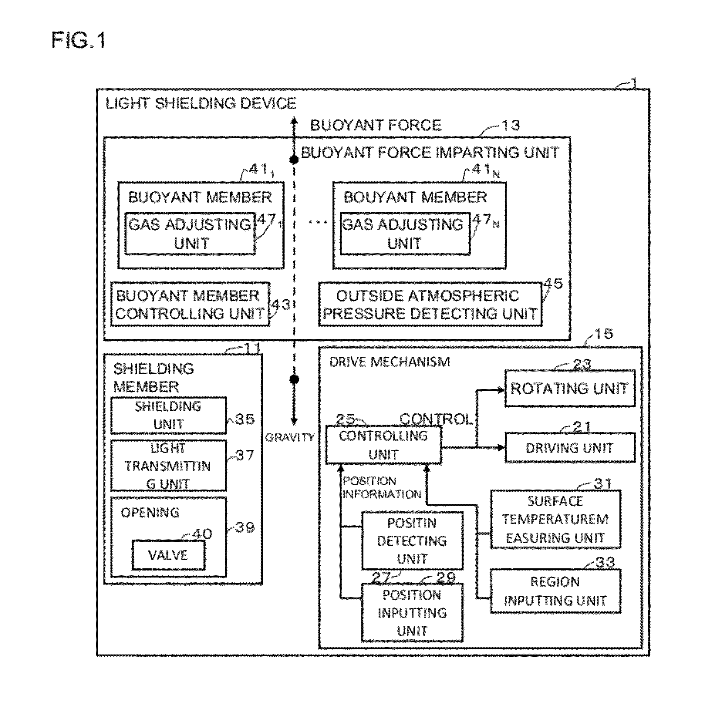
[0032]The light shielding device is large, and provided with a float function by a buoyant force imparting unit, a sunlight shield function by a shielding member, and a movement function by a drive mechanism. Characteristics of the functions are such that, for example, the float function is configured to cause the device to float as a disc-shaped balloon by filling helium, and configured by an outer skin such as vinyl of 100 g / m2, the sunlight shield function is configured to reflect and radiate sunlight into the space, and the movement function is configured to move the device by electric propellers, and to be remotely controlled by position measurement and a communication function based on a GPS function.
[0033]For example, a surface area of the Earth is 5.1×10⁸ and about at least 1,600,000 disc-shaped light shielding devices whose diameter is 1000 m is necessary in order to cast a shadow over 1% of the surface to prevent the warming. This means that energy of about 1.3×10¹² kilowatt-hour is constantly radiated out of the Earth every hour, and corresponds to a state in which the energy equals to electric power generated by about 1,300,000 nuclear generators is constantly removed to cool the Earth.
[0034]Using the light shielding device according to the present invention, it is possible to reduce the sunlight received by the Earth, and thereby immediately cooling the Earth. Even if the cooling by the present invention becomes unnecessary in the future, it is possible to terminate the cooling only by bringing the light shielding device down to the ground. In an operation according to the present invention, no CO2 is emitted, and no energy is necessary for operation.

Problems solved by technology

Typhoons are growing larger and larger and guerilla rains (sudden fierce downpours) occur due to urban heat islands.
By contrast, since a part of the cause of guerilla rains occurring in the urban center is a large amount of heat generation due to power consumed for cooling and lighting in buildings in summer in the concerned area, it is difficult to predict occurrence of such guerilla rains, and therefore a method of predicting or preventing occurrence of guerilla rains has not been materialized yet.

Method used


Image

  • Light shielding device and light shielding method
  • Light shielding device and light shielding method
  • Light shielding device and light shielding method

Examples

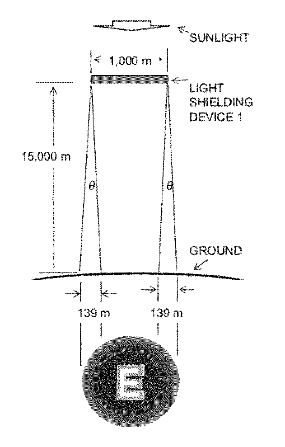
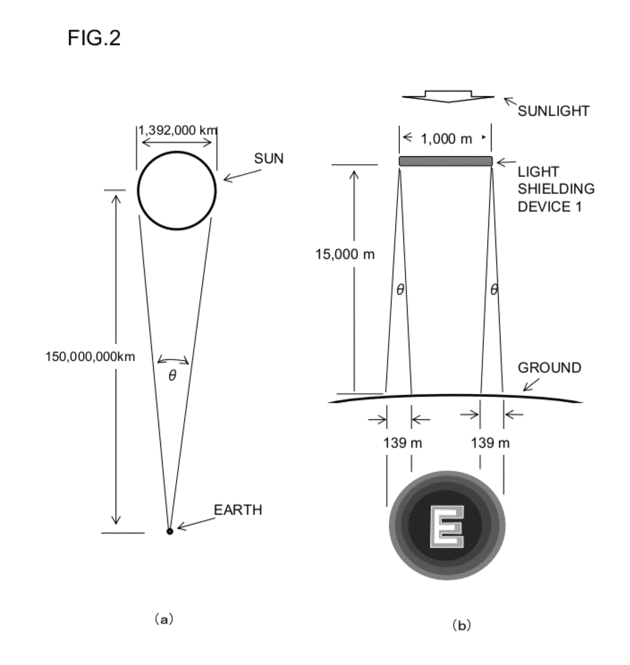

embodiment 1

[0106]FIG. 6 shows the light shielding device according to an embodiment 1 of the present invention viewed from its side, and FIG. 7 shows this light shielding device viewed from its top. The following describes the embodiment 1 with reference to FIG. 6 and FIG. 7.

[0107]Referring to FIG. 6, the light shielding device includes a buoyant member 110, and a shielding member 120. Referring to FIG. 7, the shielding member 120 is configured by a light shielding unit 121, and a light transmitting unit 122. The light shielding unit 121 has an aluminum foil on its surface facing toward the Sun, and reflects sunlight to cast a shadow. The light transmitting unit 122 is made of transparent vinyl, and configured as a sunlight transmitting unit that transmits the sunlight. It should be noted that the gas lighter than the air such as helium is filled within the shielding member 120.

[0108]Further, as shown in FIG. 7, the light shielding device is provided with buoyant member 123 in which the air on...

embodiment 2

[0113]FIG. 8 shows the light shielding device according to an embodiment 2 of the present invention viewed from its side, and FIG. 9 shows this light shielding device viewed from its top. The following describes the embodiment 2 with reference to FIG. 8 and FIG. 9, in particular from the viewpoint of differences from the embodiment 1. The same numerals shown in FIG. 8 and FIG. 9 with those of the embodiment 1 denote components of the same characteristics.

[0114]The light shielding device in the embodiment 2 is configured such that the light shielding device according to the embodiment 1 is additionally provided with a drive mechanism 130 which has a function of increasing and decreasing the buoyant force produced in the buoyant member 110. Similarly to that shown in FIG. 1, the drive mechanism 130 includes a driving unit configured to drive the shielding member 120, a movement controlling unit configured to control the driving unit, and a position detecting unit configured to detect ...


PUM


Abstract

Provided is a large scale light shielding device and a light shielding method for controlling weather. A light shielding device 1 includes a shielding member 11 that shields a part or all of spectrums of sunlight, a buoyant force imparting unit 13 having buoyant members 41, and a drive mechanism 15. The shielding member 11 includes, in order to shield the part or all of the spectrums of the sunlight, a light shielding unit 35 and a light transmitting unit 37. The drive mechanism 15 includes a driving unit 21 that settles or changes a position of the light shielding device 1, and a controlling unit 25 for the driving unit 21. Buoyant force is produced by the buoyant members 41, and imparted to the light shielding device 1 in a direction opposite of gravity due to an own weight of the main body. A magnitude of the buoyant force produced by the buoyant members 11 depends on a magnitude of gravity acting on the gas that is pushed aside by the buoyant members 11, and it is possible to cause the light shielding device 1 to float.

Description

TECHNICAL FIELD[0001]The present invention relates to light shielding devices and light shielding methods, in particular, a light shielding device and a light shielding method capable of shielding sunlight in order to control weather.BACKGROUND ART[0002]In recent years, in order to reduce the worldwide CO2 emissions along with the global warming, various actions are taken energetically on a global basis including continued researches and developments, such as conversion of CO2 into organic compounds by such as afforestation, as well as establishment of rules such as regulations of CO2 emissions. In addition, extreme weather believed to be resulted from the global warming has been experienced. Typhoons are growing larger and larger and guerilla rains (sudden fierce downpours) occur due to urban heat islands.[0003]In order to limit the damage caused by the extreme weather, various researches and developments are continued. Among others, technology for predicting typhoon movement and a...

Claims


Application Information

Patent Timeline
Patent Type & Authority Applications(United States)
IPC IPC(8): G02B7/183G02B7/188
CPCA45B3/02
Inventor MURAKAMI, HIDEYO
Owner MURAKAMI HIDEYO
Learn More