
Refrigerating device

Inactive Publication Date: 2005-04-19
DAIKIN IND LTD
View PDF15 Cites 1 Cited by
  • Summary
  • Abstract
  • Description
  • Claims
  • Application Information

AI Technical Summary

Benefits of technology

[0011]An object of the present invention is to provide an energy-saving type refrigerating device capable of preventing global warming, allowing communication pipe diameters to be reduced and the number of types of the communication pipe diameters to be reduced while COP of over COP obtained when R22 is used is provided by using, as refrigerant, R32 with small global warming potential (GWP).
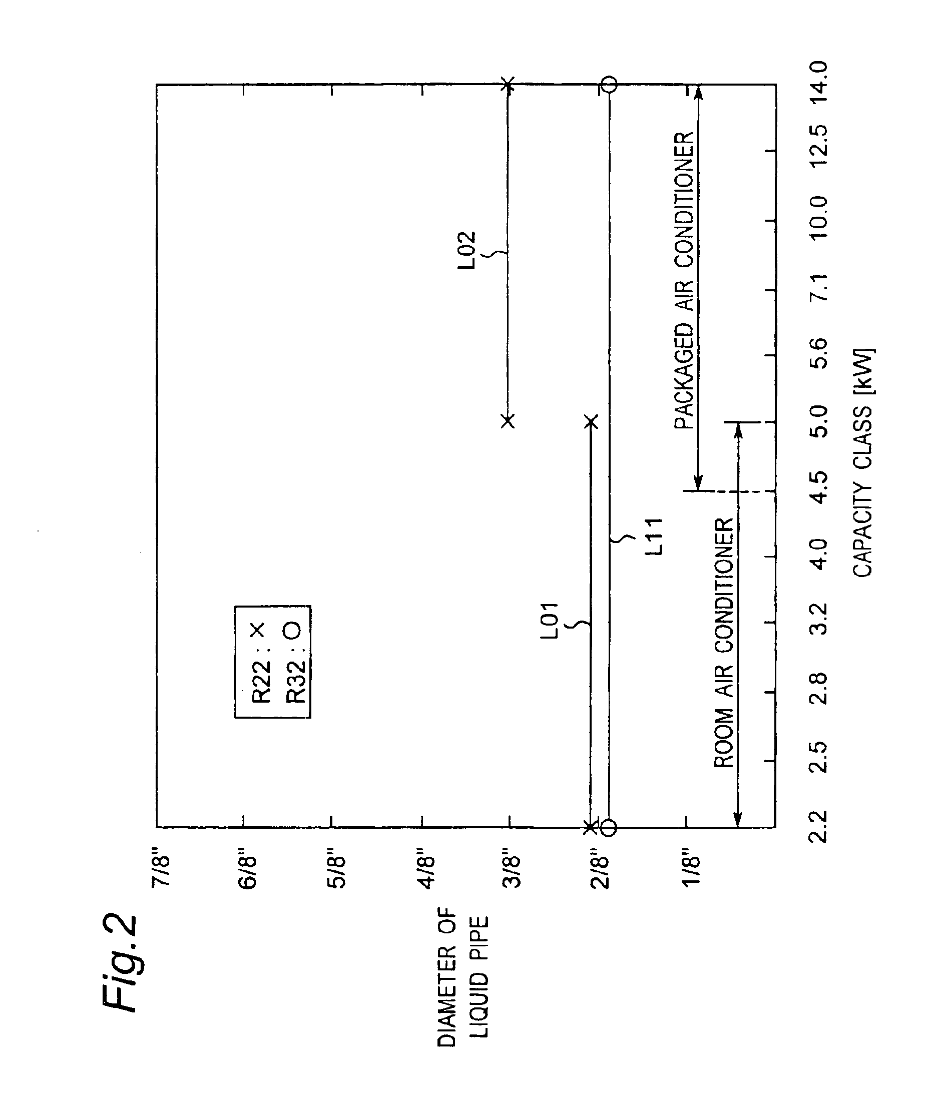
[0015]In the refrigerating device, R32 is used as refrigerant and the diameters of the first communication pipe (liquid pipe) and the second communication pipe (gas pipe) are set to {fraction (2 / 8)}″ and ⅜″, respectively, in the refrigerating capacity range of 2.2 to 5.6 kW. The diameter of the first communication pipe is the same as that in conventional devices, but the diameter of the second communication pipe is reduced in comparison with the diameters (including {fraction (4 / 8)}″) in the conventional devices because the diameter of the second communication pipe is set only to ⅜″. The diameters of the first communication pipe and the second communication pipe are respectively set to one type in the refrigerating capacity range of 2.2 to 5.6 kW. Thus, the number of types of the diameters of the communication pipes is reduced in comparison with that in the conventional devices. As a result, production control of refrigerating devices is facilitated. Besides, COP equivalent to or larger than COP obtained in the case of R22 is obtained by optimizing a quantity of refrigerant.
[0017]In this refrigerating device, R32 is used as refrigerant and the diameters of the first communication pipe (liquid pipe) and the second communication pipe (gas pipe) are set to {fraction (2 / 8)}″ and {fraction (4 / 8)}″, respectively, in the refrigerating capacity range of 4.5 to 7.1 kW. The diameter of the first communication pipe is reduced in comparison with the diameters (including ⅜″) in the conventional devices because the diameter of the first communication pipe is set only to {fraction (2 / 8)}″. Besides, the diameter of the second communication pipe is reduced in comparison with the diameters (including ⅝″) in the conventional devices because the diameter of the second communication pipe is set only to {fraction (4 / 8)}″. The number of types of the diameters of the communication pipes is reduced in comparison with that in the conventional devices because the diameters of the first communication pipe and the second communication pipe are respectively set to one type in the refrigerating capacity range of 4.5 to 7.1 kW. As a result, production control of refrigerating devices is facilitated. Besides, COP equivalent to or larger than COP obtained in the case of R22 is obtained by optimizing a quantity of refrigerant.
[0019]In this refrigerating device, R32 is used as refrigerant and the diameters of the first communication pipe (liquid pipe) and the second communication pipe (gas pipe) are set to {fraction (2 / 8)}″ and ⅝″, respectively, in the refrigerating capacity range of 7.1 to 14.0 kW. The diameter of the first communication pipe is the same as that in conventional devices, but the diameter of the second communication pipe is reduced in comparison with the diameters (including {fraction (6 / 8)}″) in the conventional devices because the diameter of the second communication pipe is set only to ⅝″. The diameters of the first communication pipe and the second communication pipe are respectively set to one type in the refrigerating capacity range of 7.1 to 14.0 kW. Thus, the number of types of the diameters of the communication pipes is reduced in comparison with that in the conventional devices. As a result, production control of refrigerating devices is facilitated. Besides, COP equivalent to or larger than COP obtained in the case of R22 is obtained by optimizing a quantity of refrigerant.

Problems solved by technology

Especially, in terms of ozonosphere protection among the global environmental problems, R22 (HFC22) which has conventionally been used is not suitable refrigerant since R22 has a high ODP (Ozone Depletion Potential).
In such a refrigerating device, on the other hand, there occur phenomena such as increase in pressure and discharge temperature relative to those with use of R22.
In addition, slightly flammable R32 has a problem of difficulty in establishing a consensus on safety thereof.
Therefore, the industrial world has not employed R32 as alternative refrigerant for actual products.
This is because the flow rate i.e. velocity of refrigerant increases and thereby pressure loss increases in a pipe having a same diameter.
The larger a diameter of a pipe is, however, the more extensive and the more difficult piping work such as connection of and work on the pipe is.
On the other hand, a large number of types of pipe cause a problem of bothersome production control of air conditioners.

Method used


Image

  • Refrigerating device
  • Refrigerating device
  • Refrigerating device

Examples


Embodiment Construction

[0027]Hereinbelow, a refrigerating device of the invention will be described in detail with reference to a preferred embodiment shown in the drawings.

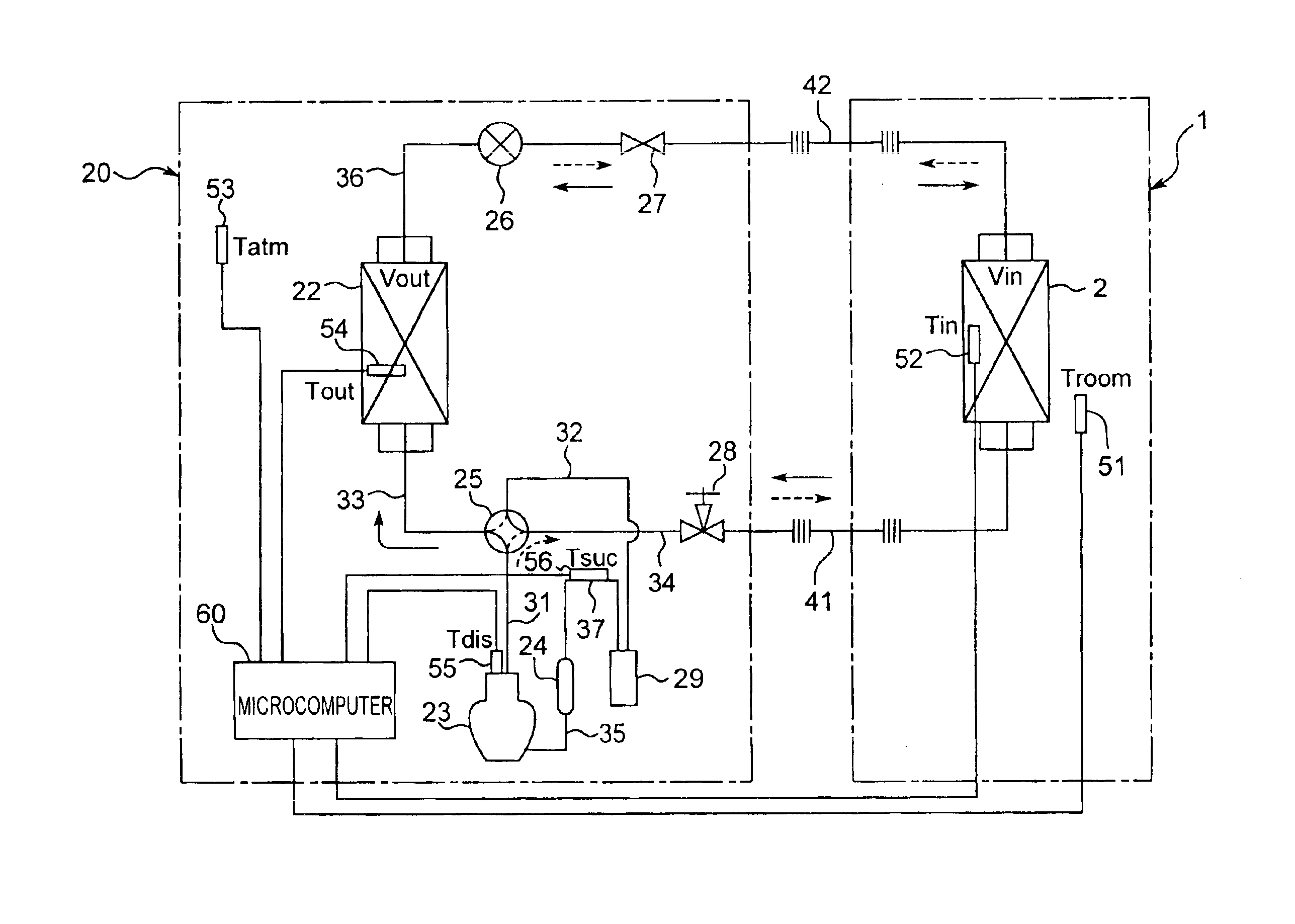
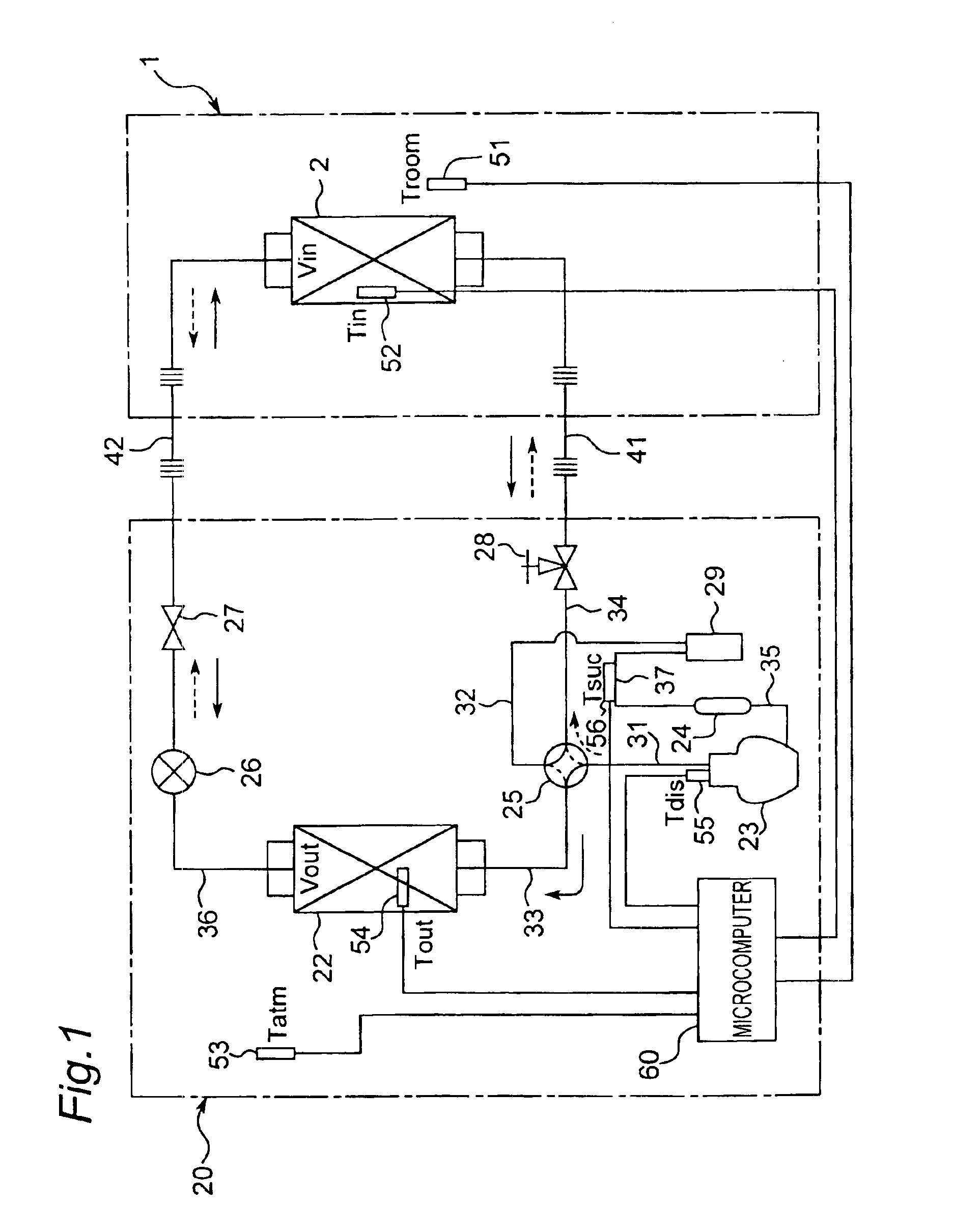
[0028]FIG. 1 shows a schematic configuration of an air conditioner for explaining the invention. In the air conditioner, a refrigerant circuit is composed of an outdoor unit 20 and an indoor unit 1 that are connected to each other by refrigerant pipes 41 and 42, wherein R32 as refrigerant is circulated through the refrigerant circuit. In the indoor unit 1, an indoor heat exchanger 2 is housed as a second heat exchanger. In the outdoor unit 20, there are housed a compressor 23 for compressing and discharging refrigerant (R32), a four-way valve 25 for switching refrigerant passages, an outdoor heat exchanger 22 as a first heat exchanger, a motor-operated expansion valve 26, an accumulator 24 for gas-liquid separation of returned refrigerant, a receiver 29 for adjusting quantity of refrigerant for cooling and heating, and a microcomputer ...


PUM


Abstract

An energy-saving refrigerating device is capable of preventing global warming, allowing a communication pipe diameter to be reduced and the number of types of the communication pipe diameters to be reduced while a COP of over the COP obtained when R22 is used is provided by using R32 with small global warming potential (GWP). The refrigerating device includes a compressor, a first heat exchanger, an expansion device, and a second heat exchanger. The diameters of first and second communication pipes are set to {fraction (2 / 8)} in. and ⅜ in., respectively, in the refrigerating capacity range of 2.2 to 5.6 kW. The diameters of the first and second communication pipes are set to {fraction (2 / 8)} in. and {fraction (4 / 8)} in., respectively, in the refrigerating capacity range of 4.5 to 7.1 kW. The diameters of the first and second communication pipes are set to {fraction (2 / 8)} in. and ⅝ in., respectively, in the refrigerating capacity range of 7.1 to 14.0 kW.

Description

[0001]This application is a Divisional of co-pending application Ser. No. 10 / 169,224 filed on Jun. 27, 2002 and for which priority is claimed under 35 U.S.C. § 120. application Ser. No. 10 / 169,224 is the national phase of PCT International Application No. PCT / JP00 / 08952 filed on Dec. 18, 2000 under 35 U.S.C. § 371. The entire contents of each of the above-identified applications are hereby incorporated by reference. This application also claims priority of Application Nos. 11-373350 and 2000-230934 both filed in Japan on Dec. 28, 1999 and Jul. 31, 2000, respectively under 35 U.S.C. § 119.TECHNICAL FIELD[0002]The present invention relates to a refrigerating device and more particularly to a refrigerating device in which R32 (a chemical formula CH2F2) or mixed refrigerant containing at least 70 percent R32 by weight is used as alternative refrigerant to R22 (a chemical formula CHClF2).BACKGROUND ART[0003]In a refrigerating device or an air conditioner of split type that execute refrig...

Claims


Application Information

Patent Timeline
IPC IPC(8): C09K5/00C09K5/04F25B41/00F25B9/00F25B13/00F25B1/00
CPCC09K5/045F25B41/003F25B9/002C09K2205/122C09K2205/24F25B2500/01F25B13/00F25B2400/12Y02P20/10F25B41/40F28F1/006
Inventor TAIRA, SHIGEHARU
Owner DAIKIN IND LTD
Learn More