User interface system and method using thermal imaging

Active Publication Date: 2012-03-29
SONY COMPUTER ENTERTAINMENT INC
View PDF7 Cites 78 Cited by
  • Summary
  • Abstract
  • Description
  • Claims
  • Application Information

AI Technical Summary

Problems solved by technology

Keyboard interfaces are good for entering text but less useful for entering directional commands.
Joysticks and mice are good for entering directional commands and less useful for entering text.
Such augmentation can increase the cost of

Method used


Image

  • User interface system and method using thermal imaging
  • User interface system and method using thermal imaging
  • User interface system and method using thermal imaging

Examples


embodiments

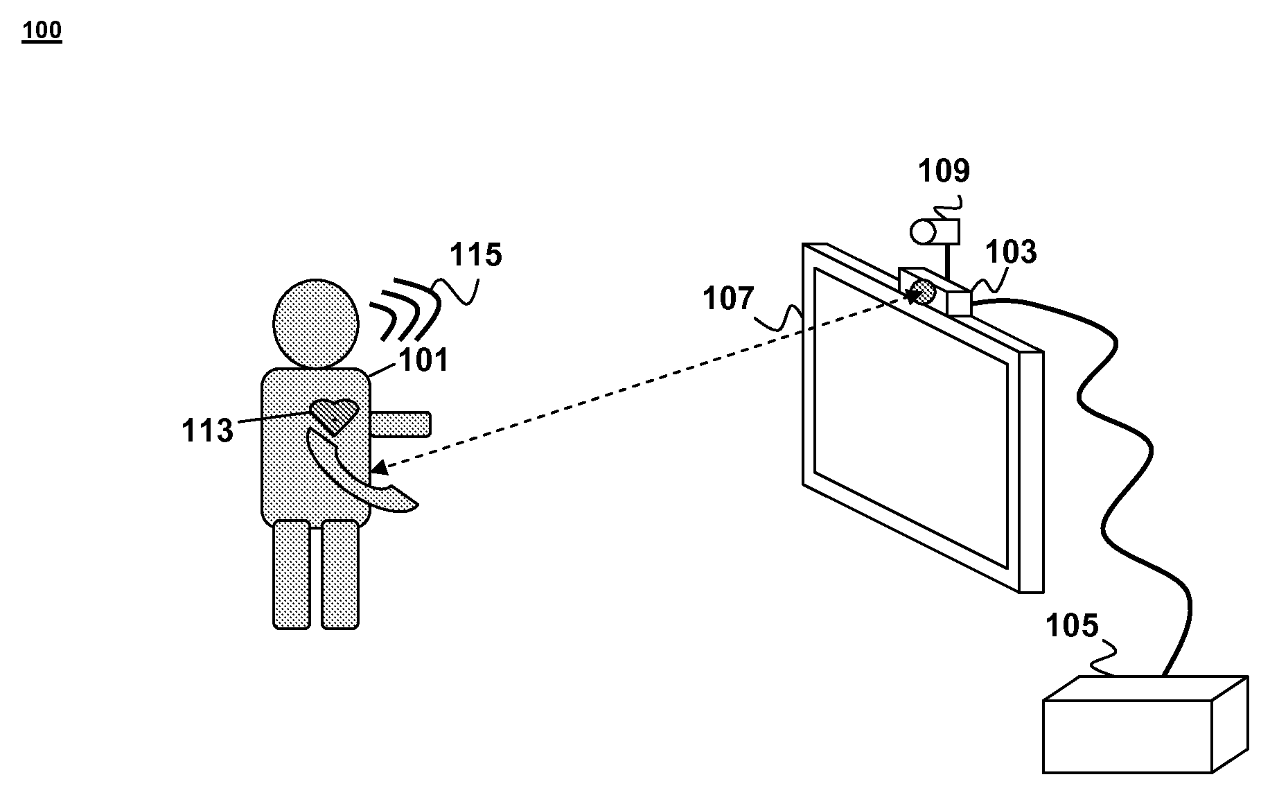
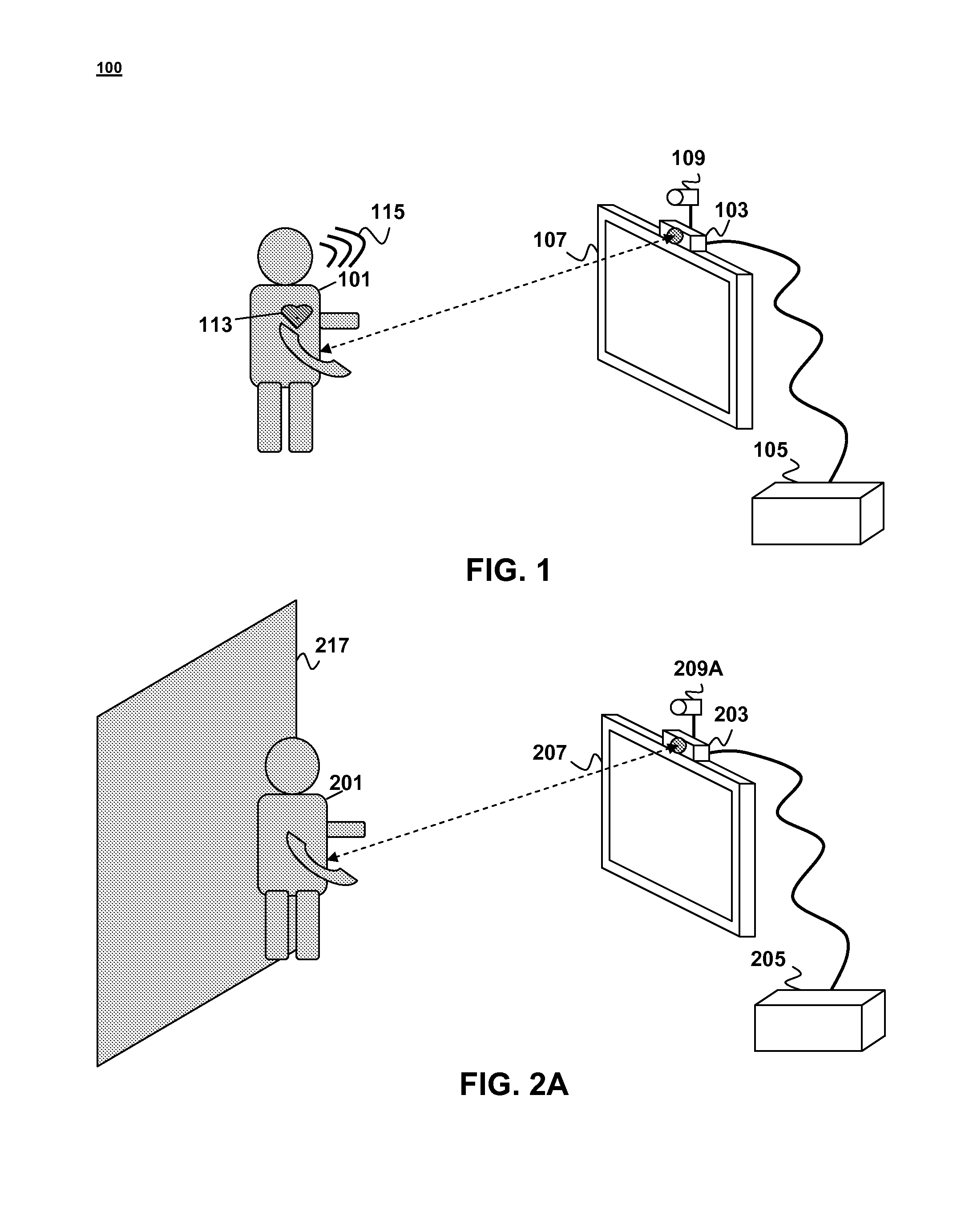
[0017]Examples of embodiments of the invention may be understood by first referring to FIG. 1. FIG. 1 is a schematic diagram illustrating a possible system for controlling a computer program using a thermal imaging interface. The system 100 generally includes a thermographic camera 103 coupled to a computer processing system 105. The thermographic camera 103 may be positioned proximate a video display 107 that is coupled to the processing system 105 such that the user 101 faces the camera 103 when facing the display 107.

[0018]Use of a thermographic camera 103 to track various user characteristics (e.g., heart rate, respiration rate) is particularly advantageous because it avoids the need to put sensors on the user's body. Additional information about the user may be obtained with much less intrusion. Tracking the heart rate of a user through thermographic imaging avoids the need for attaching a pulse monitor to the body. Likewise, tracking the respiration rate through thermographic ...


PUM


Abstract

A thermal imaging interface for control of a computer program may obtain one or more thermal infrared images of one or more objects with one or more thermographic cameras. The images may be analyzed to identify one or more characteristics of the objects. Such characteristics may be used as a control input in the computer program.

Description

CLAIM OF PRIORITY[0001]This application is a continuation-in-part and claims the priority benefit of commonly-assigned co-pending U.S. patent application Ser. No. 12 / 889,347, entitled BLOW TRACKING INTERFACE SYSTEM AND METHOD, to Ruxin Chen and Steven Osman, filed Sep. 23, 2010, the entire contents of which are incorporated herein by reference.FIELD OF THE INVENTION[0002]Embodiments of this invention are directed to user interfaces for control of computer systems and more specifically to user interfaces that use thermal imaging to provide or augment control input to a computer program.BACKGROUND OF THE INVENTION[0003]There are a number of different control interfaces that may be used to provide input to a computer program. Examples of such interfaces include well-known interfaces such as a computer keyboard, mouse or joystick controller. Such interfaces typically have analog or digital switches that provide electrical signals that can be mapped to specific commands or input signals ...

Claims


Application Information

Patent Timeline
IPC IPC(8): H04N5/33
CPCG01S11/12G06F3/011H04N5/33G06F21/32G06F3/017
Inventor CHEN, RUXINOSMAN, STEVEN
Owner SONY COMPUTER ENTERTAINMENT INC
Why Eureka
Try Eureka