
Target marker having quantum cascade laser for thermally marking a target

a target marker and quantum cascade technology, applied in the field of target markers, can solve the problems of low temperature cooling, and none of these lasers provide for a handheld, portable configuration operable at ambient or room temperatur

Active Publication Date: 2010-06-08
LMD APPL SCI LLC
View PDF14 Cites 25 Cited by
  • Summary
  • Abstract
  • Description
  • Claims
  • Application Information

AI Technical Summary

Benefits of technology

[0013]The present target marker provides a portable handheld or weapons mounted device including firearm-mounted device which can selectively create a beam of thermal infrared radiation having a wavelength which is viewable in a thermal imaging device. The target marker further provides for operation in a robust configuration at ambient temperatures found in field environments.

Problems solved by technology

However, these devices require cooling to a low temperature.
None of these lasers provide for a handheld, portable configuration operable at ambient or room temperature.

Method used


Image

  • Target marker having quantum cascade laser for thermally marking a target
  • Target marker having quantum cascade laser for thermally marking a target
  • Target marker having quantum cascade laser for thermally marking a target

Examples


Embodiment Construction

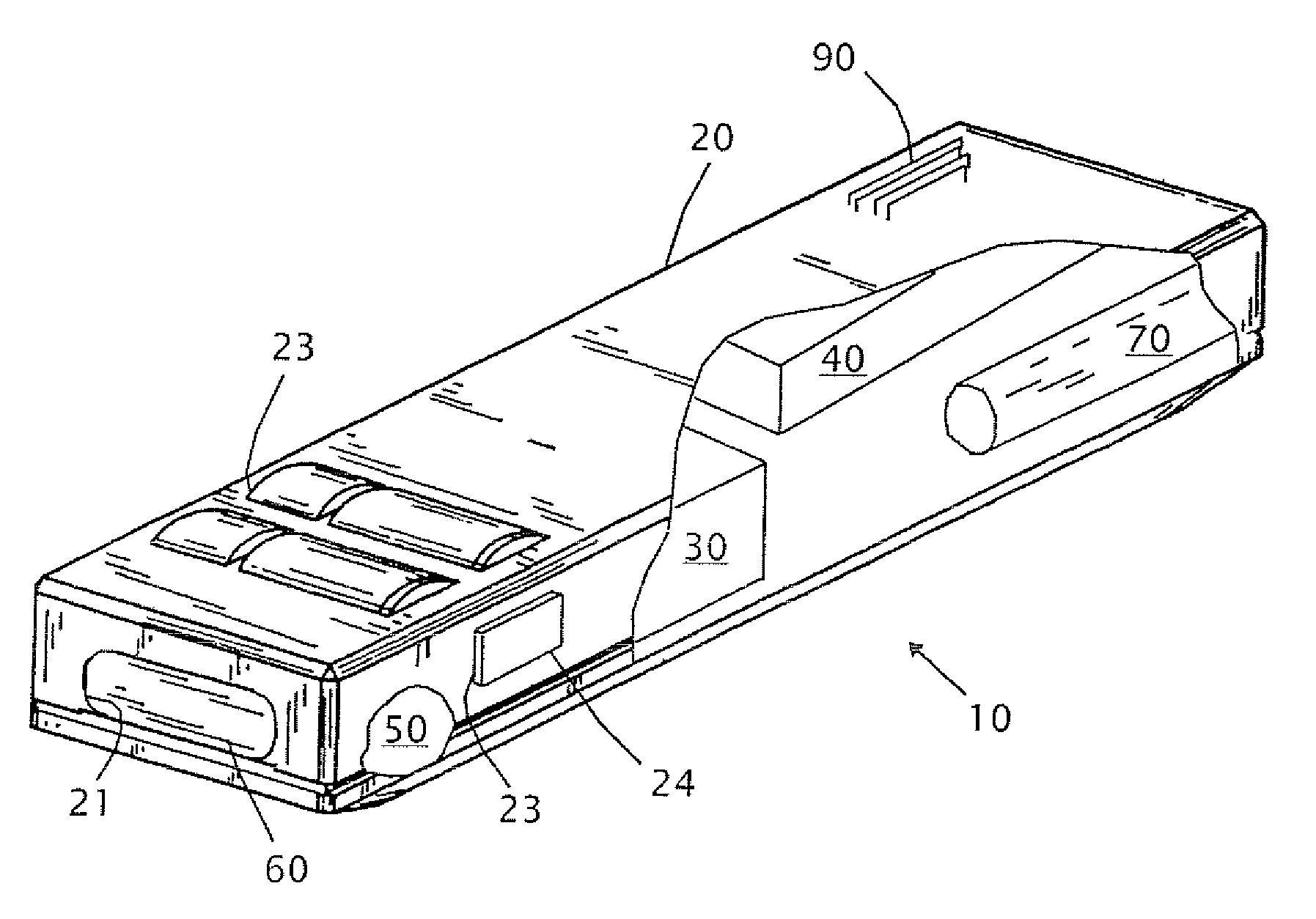
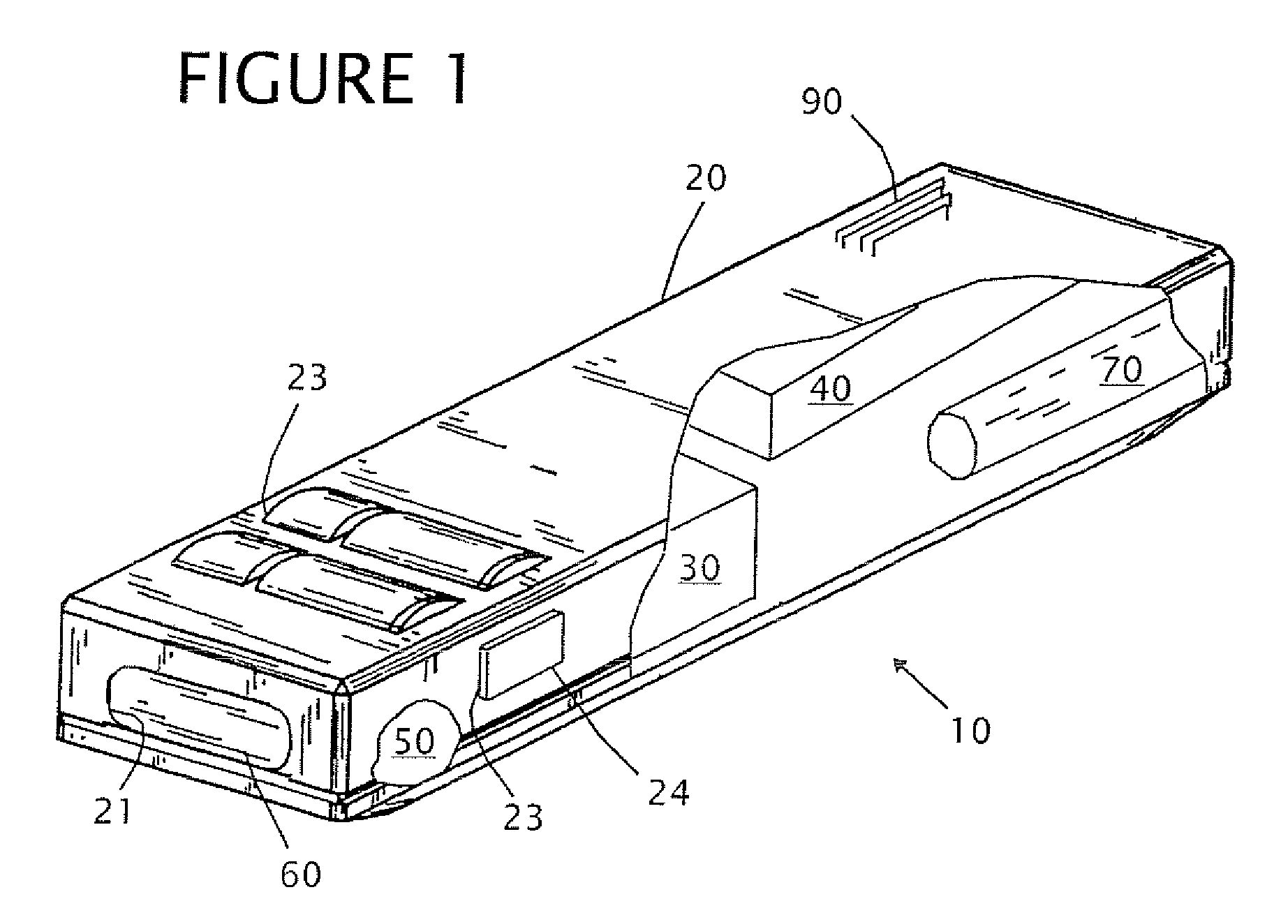
[0020]Referring to FIG. 1, a target marker 10 for use with a thermal imager 300 is shown. Although the target marker 10 is shown as a separate and independent construction from the thermal imager 300, it is contemplated the target marker can be cooperatively or integrally connected to the thermal imager. For purposes of description, the target marker 10 is set forth as a separate, remotely deployable device from the thermal imager 300.

[0021]The thermal imager 300 is known in the art and can be any of a variety of configurations. The underlying sensing and display technology of the thermal imager 300 is well-developed and employed in devices made by DRS, Raytheon, ITT or BAE. “Thermal imaging” and “thermal detection” refers to imaging and detection in the electromagnetic spectral band of 2-30 microns. “Thermal infrared beam” refers to electromagnetic energy in the 2-30 micron wavelength range.

[0022]For purposes of disclosure, a brief description of the thermal imager 300 is provided....


PUM


Abstract

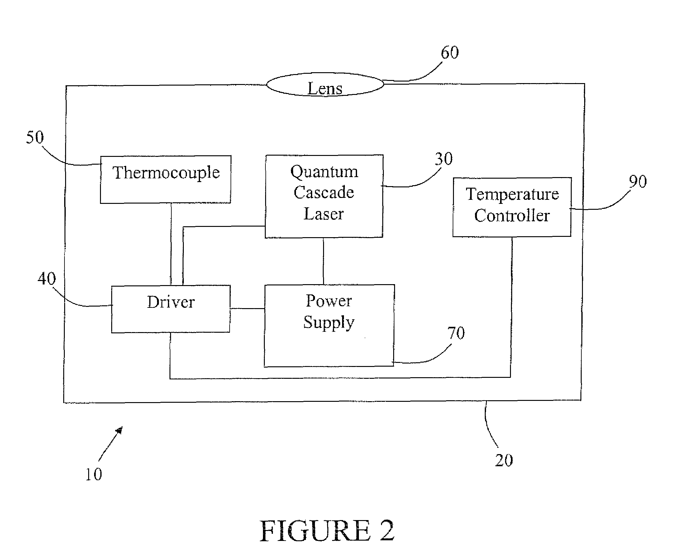
A handheld target marker is provided, wherein the target marker includes a housing retaining a quantum cascade laser, a collimating or focusing lens, a driver and a power supply. The quantum cascade laser produces a thermal infrared beam which can be selectively directed to impinge upon a target. The impinging beam is viewable by a thermal imager. The handheld target marker operates at ambient temperatures and incorporates the driver and power supply necessary for operation of the quantum cascade laser.

Description

CROSS-REFERENCE TO RELATED APPLICATIONS[0001]Not Applicable.STATEMENT REGARDING FEDERALLY SPONSORED RESEARCH OR DEVELOPMENT[0002]Not Applicable.REFERENCE TO A “SEQUENCE LISTING”[0003]Not Applicable.BACKGROUND OF THE INVENTION[0004]1. Field of the Invention[0005]The present invention relates to marking a target, and more particularly, to a handheld and / or weapon mounted device incorporating a quantum cascade laser for generating and impinging a thermal infrared beam upon a target to create a corresponding image in a thermal imager.[0006]2. Description of Related Art[0007]In contrast to image enhancement technology typically employed in “night vision,”“image intensifier” or “I2” devices, thermal imaging does not require any ambient light or supplemental infrared illumination to illuminate a target or to produce an image.[0008]That is, in a thermal imaging device, thermal infrared radiation (typically ranging from approximately 2 microns to 30 microns in wavelength) is captured and con...

Claims


Application Information

Patent Timeline
Patent Type & Authority Patents(United States)
IPC IPC(8): G01J5/00H01S3/00
CPCB82Y20/00G02B27/20H01S5/02208H01S5/005H01S5/3402H01S5/02288H01S5/02407H01S5/0617H01S5/02253
Inventor HOUDE-WALTER, SUSAN
Owner LMD APPL SCI LLC
Learn More