
Numerical-control machine-tool thermal error prediction method based on unbiased estimation splitting model and system thereof

A technology of numerical control machine tool and prediction method, which is applied to the prediction of machine tool thermal error in strong coupling temperature field, and the thermal error prediction field of numerical control machine tool based on unbiased estimation split model, which can solve the instability of thermal error model, the influence of variable coupling, Reduce thermal error prediction robustness and other issues

Active Publication Date: 2016-07-13
HEFEI UNIV OF TECH
View PDF7 Cites 21 Cited by
  • Summary
  • Abstract
  • Description
  • Claims
  • Application Information

AI Technical Summary

Problems solved by technology

However, the above mathematical modeling algorithms are seriously affected by variable coupling
Due to the complex nonlinear and time-varying characteristics of the temperature field of the machine tool, when the environment of the machine tool changes greatly, the coupling degree between temperature variables often changes greatly. If these algorithms are used to establish the thermal error model of the machine tool at this time, There will be a phenomenon that the estimated value of the model parameter changes sensitively with the change of the sample size or the increase of the number of independent variables, so that the established thermal error model is extremely unstable
[0005] In addition, the current temperature sensitive point selection method and thermal error modeling method are not required to cooperate uniformly, which also reduces the robustness of thermal error prediction to a certain extent.

Method used


Image

  • Numerical-control machine-tool thermal error prediction method based on unbiased estimation splitting model and system thereof
  • Numerical-control machine-tool thermal error prediction method based on unbiased estimation splitting model and system thereof
  • Numerical-control machine-tool thermal error prediction method based on unbiased estimation splitting model and system thereof

Examples


Embodiment

[0095] In this embodiment, the research on the thermal error prediction method is carried out for the Z direction of the spindle of the Leaderway-V450 CNC machine tool.

[0096] Below are the specific implementation steps of this embodiment:

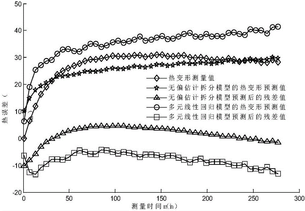
[0097] In this embodiment, the infrared thermal imager Ti200 is used to perform thermal imaging on the Leaderway-V450 CNC machine tool that has been idling at 4000rpm for one hour, and the heat source area is judged and marked, and the temperature sensor T1 is placed in each heat source area in the Z direction of the machine tool spindle ~ T9, and place the temperature sensor T10 for measuring the ambient temperature. Under the experimental conditions: the initial ambient temperature is 14.44°C, and the spindle speed is 4000rpm, the temperature value increment (ie temperature variable) of each temperature sensor and the Z-direction thermal deformation of the spindle are obtained, and the records are as follows:

[0098] Table 1 Data rec...


PUM


Abstract

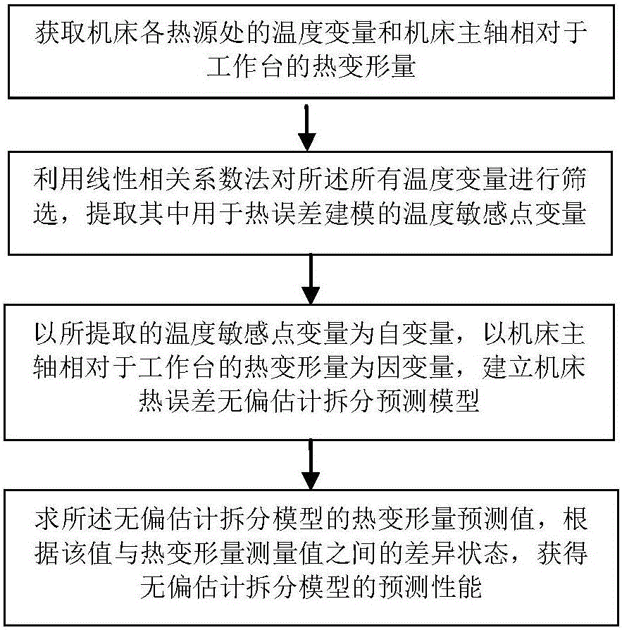
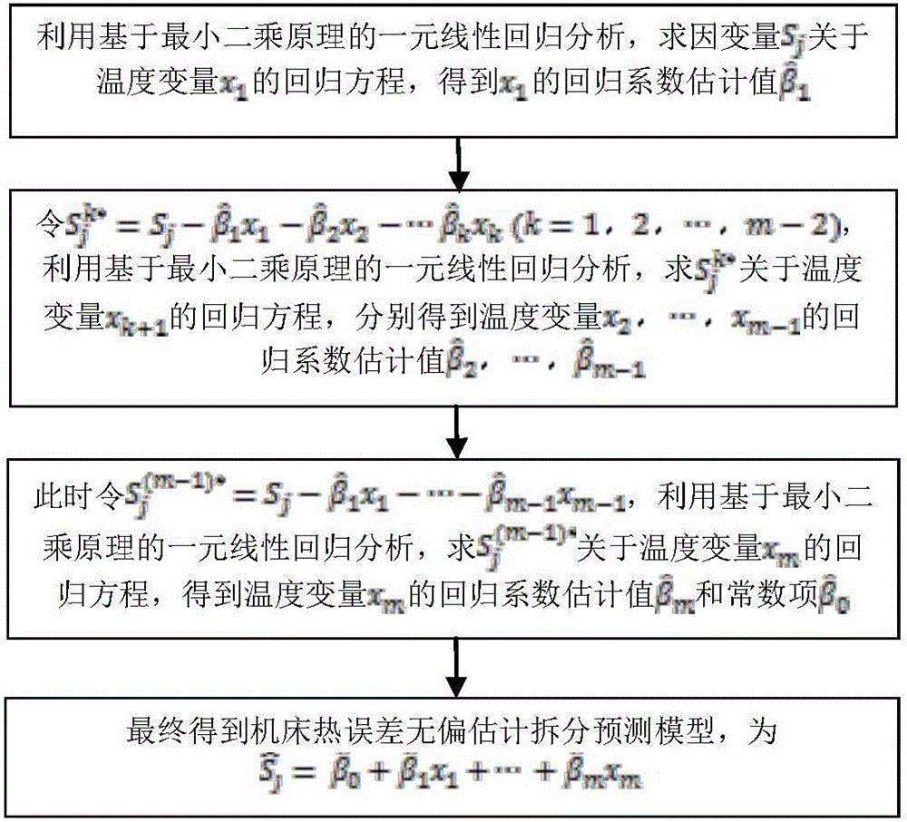
The invention discloses a numerical-control machine-tool thermal error prediction method based on an unbiased estimation splitting model and a system thereof. The prediction method comprises the following steps of 1, acquiring a temperature variable and a thermal deformation amount of a machine tool main shaft; 2, extracting a temperature sensitive point variable needed by thermal error modeling; 3, establishing a machine-tool thermal-error unbiased estimation splitting model; 4, calculating a thermal deformation amount prediction value of the unbiased estimation splitting model, and according to a difference state of the value and a thermal deformation amount measurement value, acquiring prediction performance of the unbiased estimation splitting model. The system comprises an infrared thermal imager, a temperature sensor, an eddy current displacement sensor and an industrial control computer. By using the method and the system, a coupling effect among temperature independence variables is effectively solved; and a temperature sensitive point selection method and a thermal error modeling model are cooperated and used so that prediction precision and robustness of the thermal error model are greatly increased.

Description

technical field [0001] The invention belongs to the technical field of precision machining machine tools, and relates to a thermal error prediction method and system of a numerical control machine tool based on an unbiased estimation split model, and is especially suitable for predicting the thermal error of a machine tool in a strongly coupled temperature field. Background technique [0002] With the rapid development of precision and ultra-precision machining technology, higher requirements are put forward for the machining accuracy and reliability of CNC machine tools and machining centers. During the actual processing and operation of CNC machine tools, due to the influence of factors such as friction heat, cutting heat and ambient temperature on the process system, the expansion of machine tool parts will cause thermal deformation. This thermal deformation will change the relative position between the various parts of the machine tool, causing the tool to deviate from t...

Claims


Application Information

Patent Timeline
IPC IPC(8): G05B19/404
CPCG05B19/404
Inventor 苗恩铭刘义杨思炫刘辉
Owner HEFEI UNIV OF TECH
Learn More