Surveillance system and method

a surveillance system and surveillance technology, applied in the field of surveillance technologies, can solve the problems of high power consumption, blind spots, and expensive solutions

Active Publication Date: 2012-03-29
HANGZHOU HIKVISION DIGITAL TECH
View PDF2 Cites 9 Cited by
  • Summary
  • Abstract
  • Description
  • Claims
  • Application Information

AI Technical Summary

Problems solved by technology

However, it is common for such systems to have blind spots, such as below or behind a camera.
In some cases, a plurality of cameras may be used to try to prevent blind spots but this is a costly solution.
In other systems, a camera may be powered to constantly pan and tilt to eliminate blind spots, but this uses much power and is still subject to at least temporary blind spots.

Method used


Image

  • Surveillance system and method
  • Surveillance system and method
  • Surveillance system and method

Examples


Embodiment Construction

[0008]The disclosure, including the accompanying drawings, is illustrated by way of example and not by way of limitation. It should be noted that references to “an” or “one” embodiment in this disclosure are not necessarily to the same embodiment, and such references mean at least one.

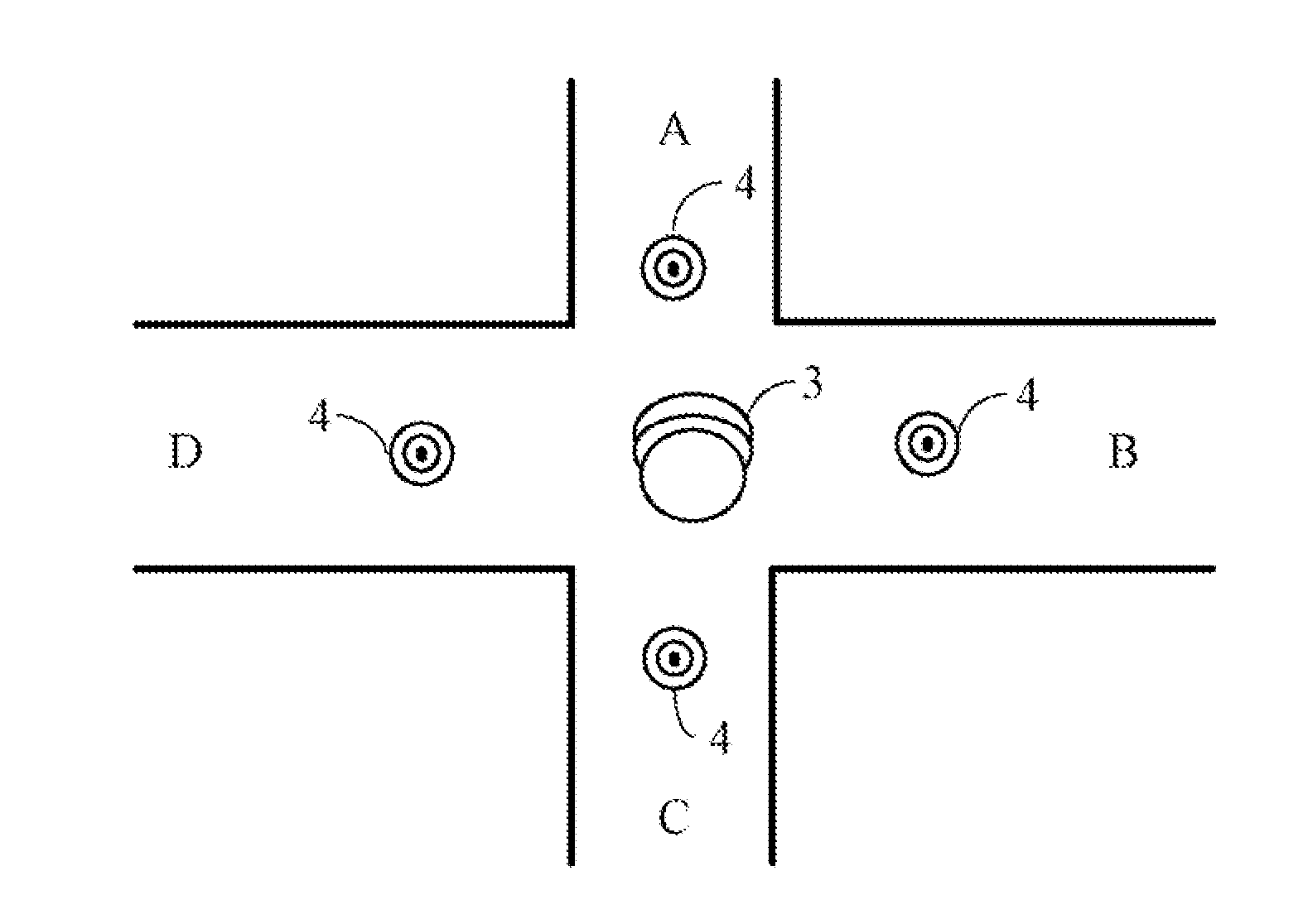
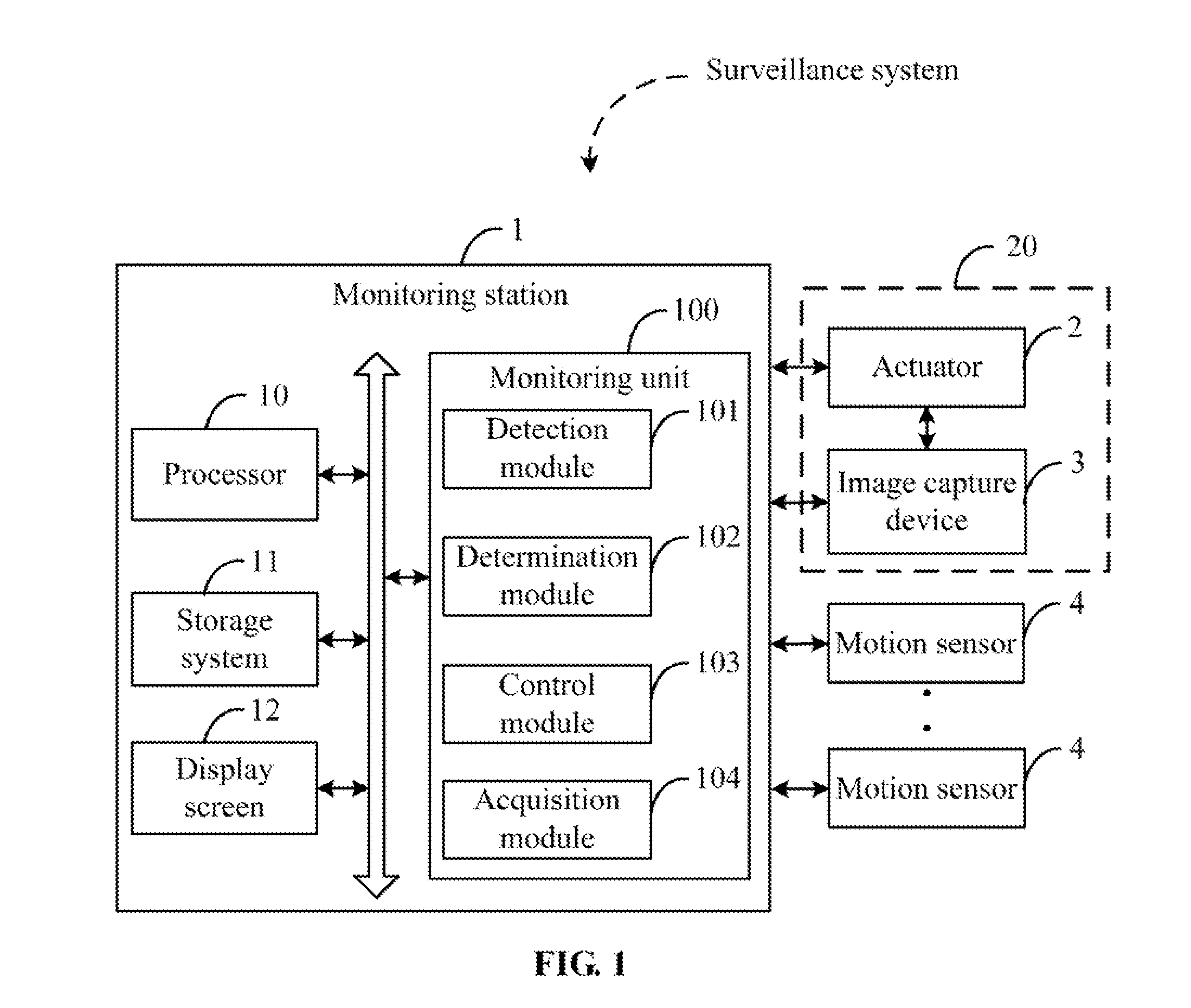
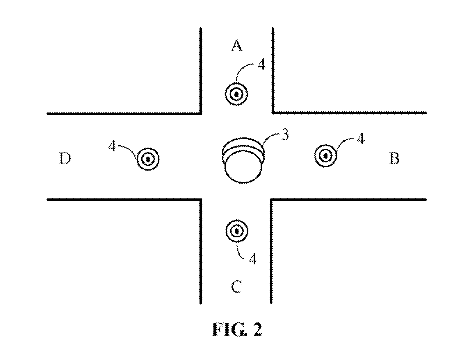
[0009]FIG. 1 is a block diagram of one embodiment of a surveillance system. The surveillance system includes a monitoring station 1, an actuator 2, an image capture device 3, and a plurality of motion sensors 4. In the embodiment, the monitoring station 1 includes a processor 10, a storage system 11, a display screen 12, and a monitoring unit 100. The monitoring unit 100 includes a detection module 101, a determination module 102, a control module 103, and an image capture module 104. Those modules may include one or more computerized instructions in the form of one or more programs that are stored in the storage system 11 or a computer-readable medium of the monitoring station 1, and executed by the p...


PUM


Abstract

A surveillance method monitors a monitored area using a monitoring station. The monitoring station in electronic communication with an actuator, an image capture device, and a plurality of motion sensors. The presence of motion in the monitored area is detected in real-time using the motion sensors. When the motion is detected, a target region in the monitored area where the motion is detected is determined, and a control signal is sent to the actuator according to the target region to control the image capture device to aim at the target region using the actuator. Real-time images of the target region are captured, and stored in a storage system of the monitoring station.

Description

BACKGROUND[0001]1. Technical Field[0002]Embodiments of the present disclosure relate generally to surveillance technologies, and more particularly, to a surveillance system and method.[0003]2. Description of Related Art[0004]Video surveillance systems are widely used in security systems to monitor areas requiring protection. However, it is common for such systems to have blind spots, such as below or behind a camera. In some cases, a plurality of cameras may be used to try to prevent blind spots but this is a costly solution. In other systems, a camera may be powered to constantly pan and tilt to eliminate blind spots, but this uses much power and is still subject to at least temporary blind spots.BRIEF DESCRIPTION OF THE DRAWINGS[0005]FIG. 1 is a block diagram of one embodiment of a surveillance system.[0006]FIG. 2 is a schematic diagram illustrating one example of placement of an image capture device and four motion sensors of the surveillance system of FIG. 1 in an area to be mon...

Claims


Application Information

Patent Timeline
Patent Type & Authority Applications(United States)
IPC IPC(8): H04N7/18
CPCH04N7/188
Inventor WU, KANGTIAN, BO
Owner HANGZHOU HIKVISION DIGITAL TECH
Why Eureka
Try Eureka