Internet visual surveillance and management technology for telecommunications, internet, cellular and other communications companies

a technology of internet visual surveillance and management technology, applied in the field of visual surveillance systems, can solve the problems of increasing hardware costs, increasing the cost of such devices, and increasing the cost of maintenance and other around expenses, and bringing additional configuration costs

Inactive Publication Date: 2012-03-29
NEO IT SOLUTIONS
View PDF5 Cites 94 Cited by
  • Summary
  • Abstract
  • Description
  • Claims
  • Application Information

AI Technical Summary

Benefits of technology

[0012]In accordance with one aspect of the exemplary embodiment, a visual surveillance system includes a plurality of surveillance gathering devices, a command and control server operatively connected to each of the plurality of surveillance gathering devices through the Internet, and one

Problems solved by technology

When multiple sites are required to be covered with cameras, the device has to be placed on each and every site, significantly increasing the hardware costs, required maintenance and other around expenses.
The costs of such device are usually high, and with every new added site, are increasing geometrically.
Most of such devices are coming in form of appliances which are limited to particular number of cameras.
This requires a purchase of a new appliances, as the number of the sites grows, which brings the additional costs of configuration, increased maintenance and overall complications of such setup.
Moreover, as most of the Internet connectivity lines are limited in bandwidth, adding more sites increases camera information throughput and requires leasing new Internet lines, which further increase the overall costs and maintenance complications.
As the device placed in particular location, the collected cameras information is limited to the users located in this site.
Due to limited Internet lines, users from other locations, including the sites with placed IP cameras, are unable, or have no convenient way to access the collected information.
Even if the appliance supports Internet access, the lines limits the concurrent number of users which can access the information.
This makes real-time collected information sharing impossible, which is especially critical for large organization.
Also, as the device

Method used


Image

  • Internet visual surveillance and management technology for telecommunications, internet, cellular and other communications companies
  • Internet visual surveillance and management technology for telecommunications, internet, cellular and other communications companies
  • Internet visual surveillance and management technology for telecommunications, internet, cellular and other communications companies

Examples


Embodiment Construction

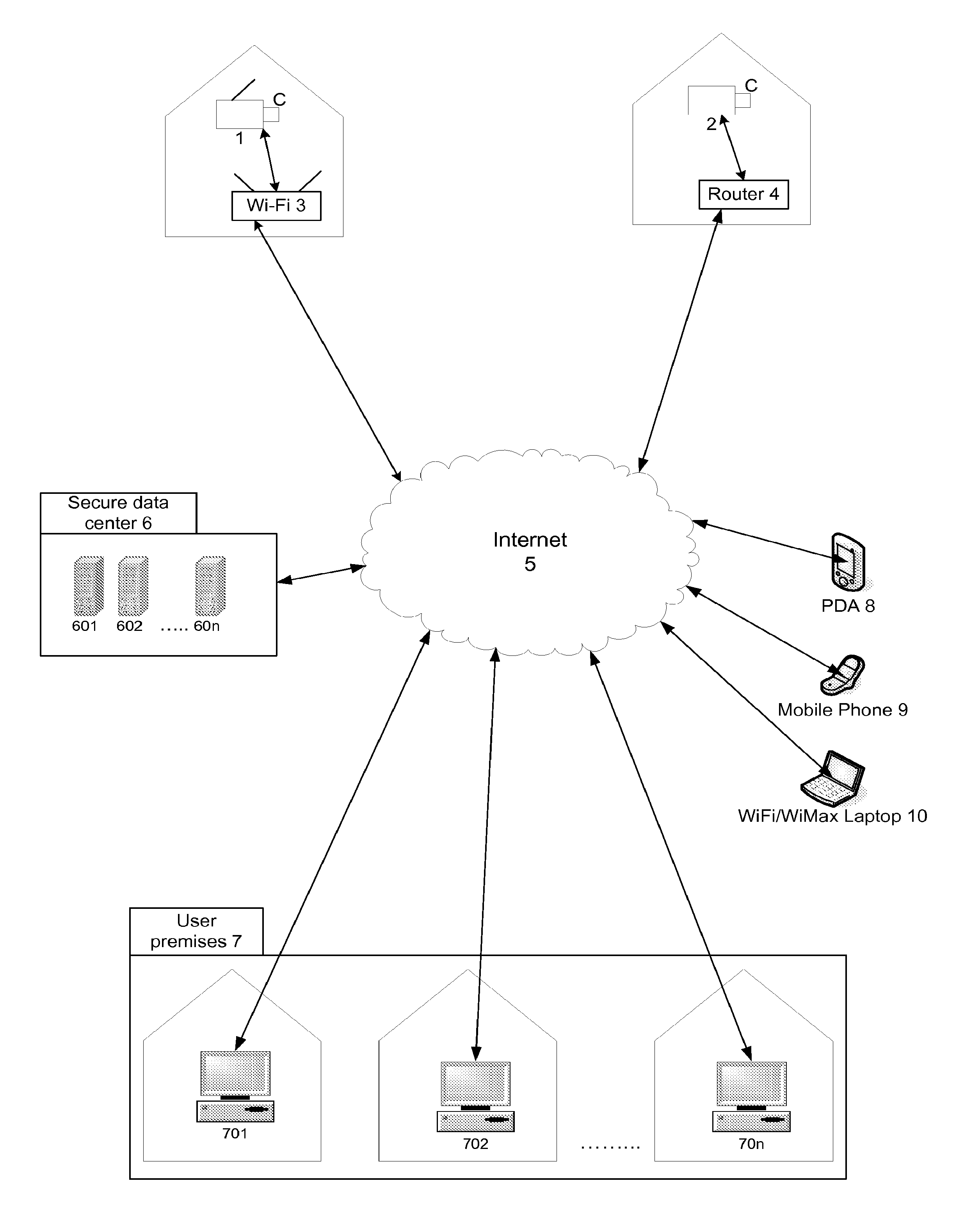
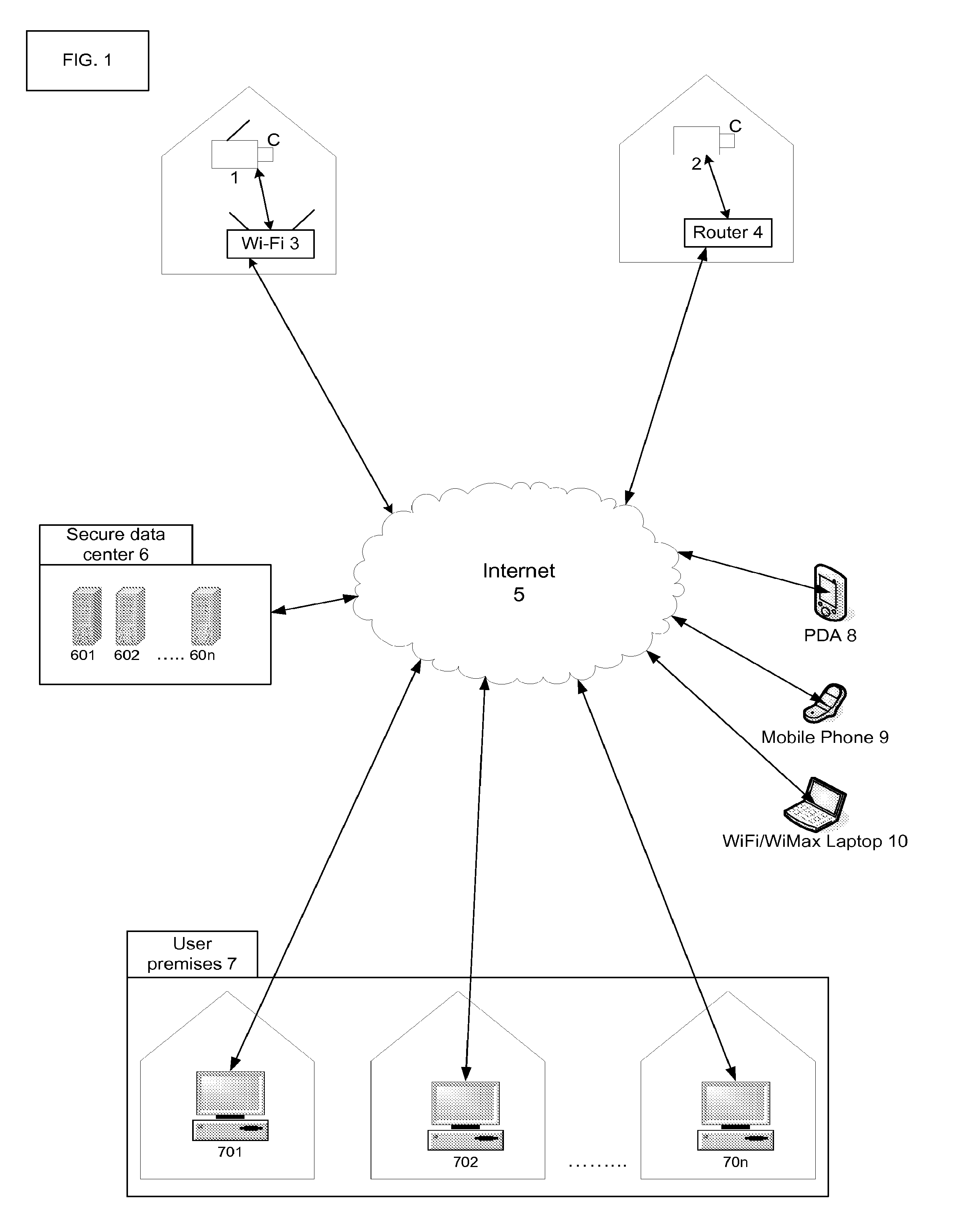
[0043]FIG. 1 shows a schematic view of a visual surveillance system in accordance with an exemplary embodiment deployed geographically. The visual surveillance system includes a plurality of surveillance gather devices such as wireless cameras 1 and wired cameras 2 installed in user sites. Cameras 1 and 2 are connected to a wireless router 3 or a wired router 4, which in turn are connected to the Internet 5. Of course it should be understood that other forms of surveillance gathering devices such as infra-red sensors, motion sensors, temperature sensors, pressure sensors, noise activated sensors, sound gathering devices and the like may also be employed.

[0044]In a remote, secure data center 6, there is a plurality of servers 601 to 60n running the invention technology in order to perform invention operations. The data center 6 is connected to the Internet 5, and enables the servers to connect to cameras 1 and 2 through routers 3 and 4, in order to gather the surveillance data.
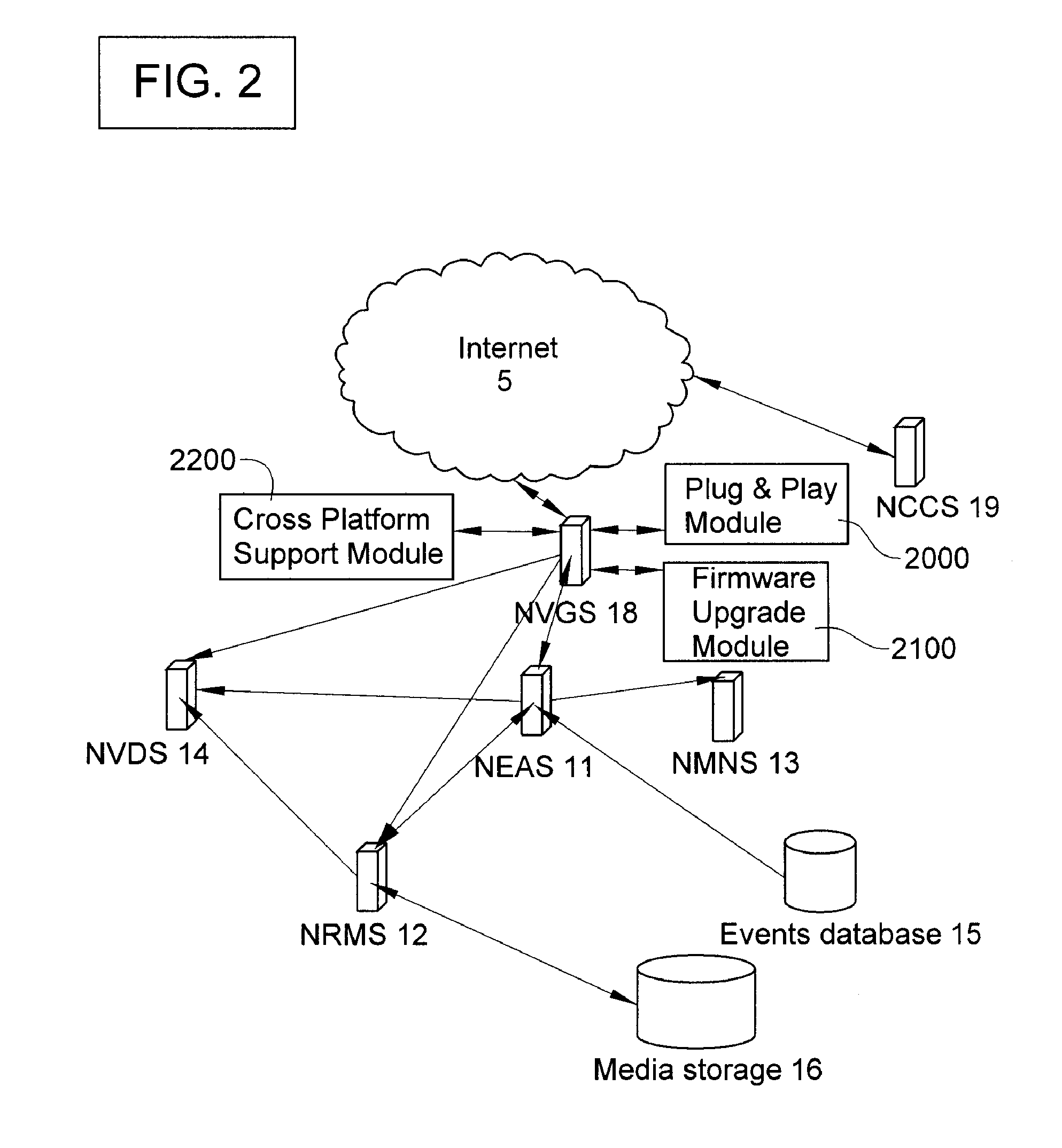
[0045]...


PUM


Abstract

A visual surveillance system includes a plurality of surveillance gathering devices, a command and control server operatively connected to each of the plurality of surveillance gathering devices through the Internet, and one or more wireless devices operatively connected to the command and control server through the Internet. The command and control server is programmed to provide wireless control and real-time monitoring of the plurality of surveillance gathering devices at the one or more wireless devices.

Description

CROSS-REFERENCE TO RELATED APPLICATIONS[0001]This application is a Continuation-in-Part of U.S. application Ser. No. 11 / 782,751 filed Jul. 25, 2007.BACKGROUND OF THE INVENTION[0002]This invention relates generally to visual surveillance systems and in particular to visual surveillance system enabling telecommunications companies and Internet providers to provide commodity visual surveillance services.[0003]The prior art surveillance technology was always developed and positioned as an on-site solution. Systems based on this technology are always requiring some sort of a central management device, in order to process the live feeds arriving from cameras. The device can be analogue or digital video recorder, or a computer with special software installed, but it always need to be present on-site, together with the cameras. When multiple sites are required to be covered with cameras, the device has to be placed on each and every site, significantly increasing the hardware costs, require...

Claims


Application Information

Patent Timeline
IPC IPC(8): H04N7/18
CPCG08B13/19656H04N5/232H04N5/23206H04N5/76H04N7/17318H04N21/4223H04N7/185H04N21/21815H04N21/2187H04N21/23439H04N21/25833H04N7/181
Inventor OSKIN, STASSAHAR, ELI
Owner NEO IT SOLUTIONS
Why Eureka
Try Eureka