3D object tracking method and apparatus

Active Publication Date: 2012-03-29
SAMSUNG ELECTRONICS CO LTD
View PDF12 Cites 7 Cited by
  • Summary
  • Abstract
  • Description
  • Claims
  • Application Information

AI Technical Summary

Benefits of technology

[0007]Therefore, it is an aspect of one or more embodiments to provide a 3D object tracking method and apparatus in which a model of an object to be tracked is divided into a plu

Problems solved by technology

Here, when the points are not correctly matched to the edge of the 3D model, the 3D rigid body tr

Method used


Image

  • 3D object tracking method and apparatus
  • 3D object tracking method and apparatus
  • 3D object tracking method and apparatus

Examples


Example

[0026]Reference will now be made in detail to embodiments, examples of which are illustrated in the accompanying drawings, wherein like reference numerals refer to like elements throughout.

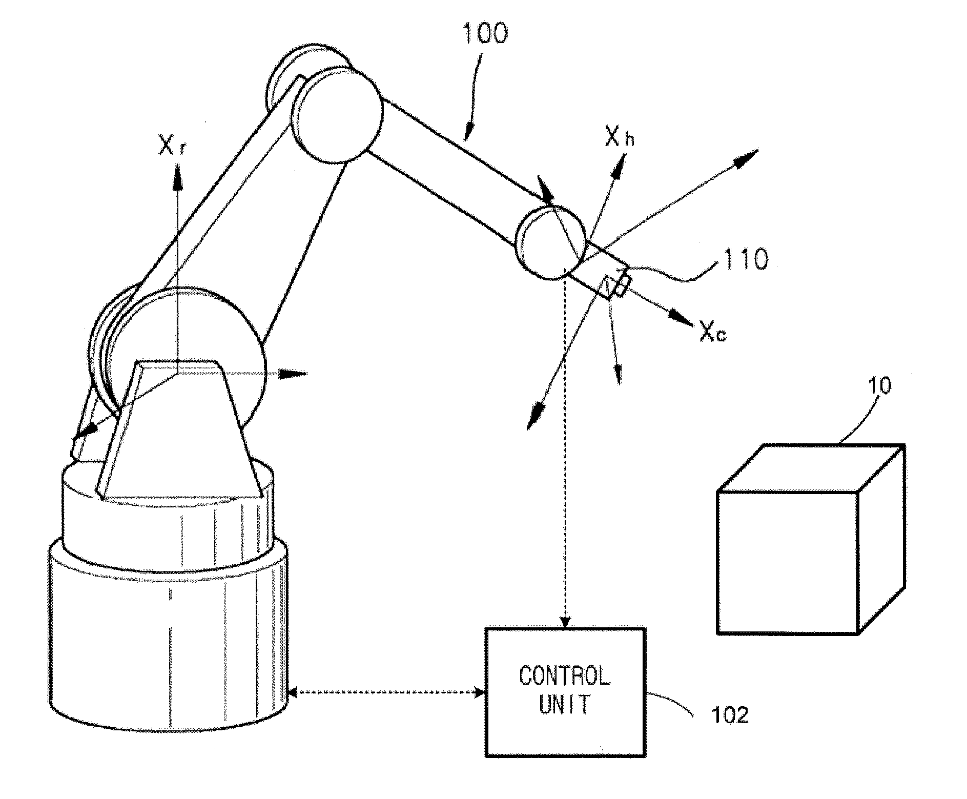
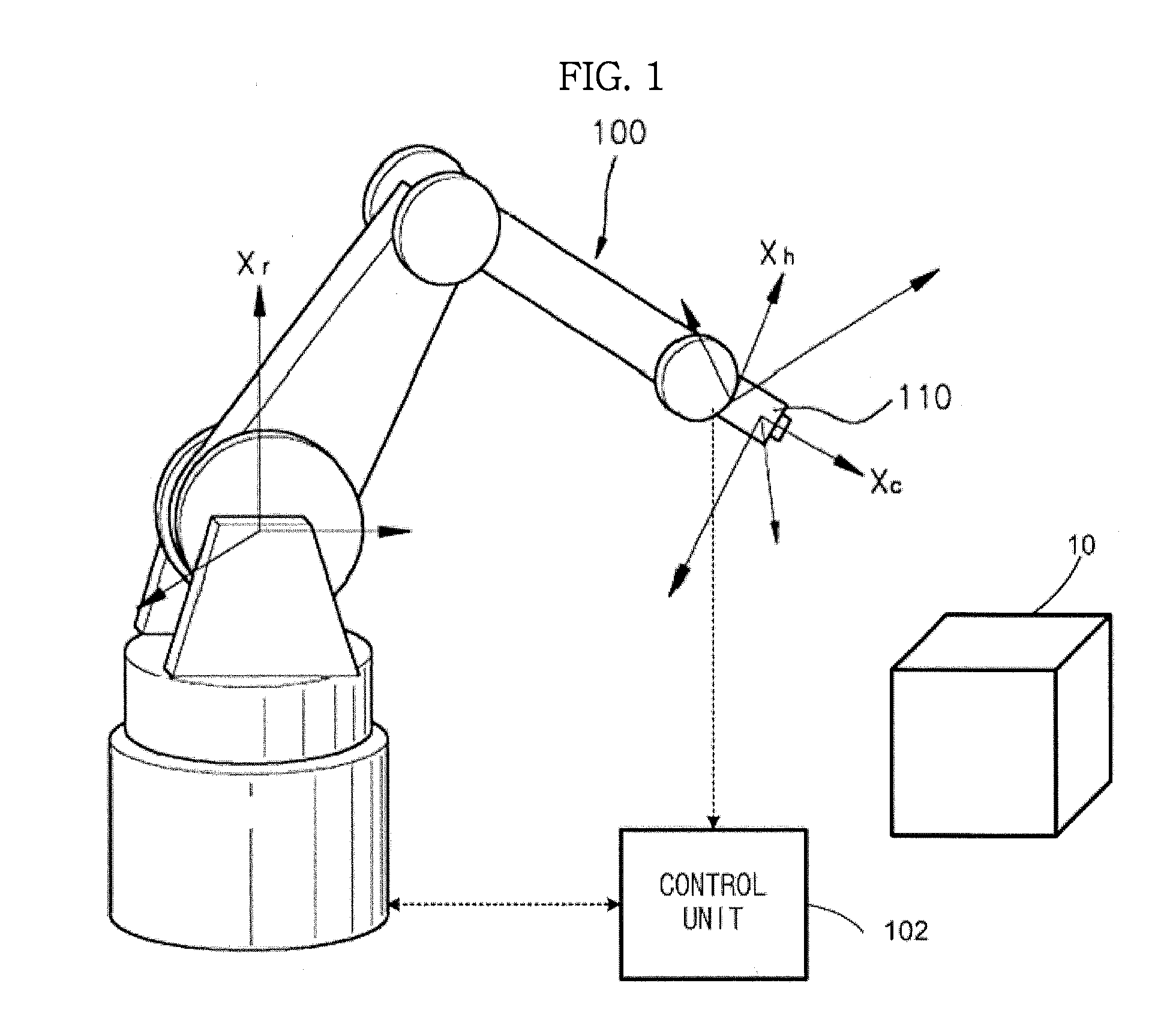
[0027]FIG. 1 is a view exemplarily illustrating an image-based robot operating system to utilize a visual servoing technique. As shown in FIG. 1, at least one Charge-Coupled Device (CCD) camera 110 (i.e., an imaging device) is attached to the tip of an industrial robot hand 100, and thus recognizes and controls movement of the robot hand 100 according to a result of analysis of an image acquired based on the movement of the robot hand 100. Here, non-described reference numeral 10 represents an object to be handled by the robot hand 100.

[0028]A control unit 102 receives an image from the camera 110, tracks the object, and generates and provides a control command to control the movement of the robot hand 100 to the robot hand 100 based on a result of the tracking, thereby allowing the robot hand 100...


PUM


Abstract

A 3D object tracking method and apparatus in which a model of an object to be tracked is divided into a plurality of polygonal planes and the object is tracked using texture data of the respective planes and geometric data between the respective planes to enable more precise tracking. The 3D object tracking method includes modeling the object to be tracked to generate a plurality of planes, and tracking the plurality of planes, respectively. The modeling of the object includes selecting points from among the plurality of planes, respectively, and calculating projective invariants using the selected points.

Description

CROSS-REFERENCE TO RELATED APPLICATIONS[0001]This application claims the benefit of Korean Patent Application No. 2010-0094134, filed on Sep. 29, 2010 in the Korean Intellectual Property Office, the disclosure of which is incorporated herein by reference.BACKGROUND[0002]1. Field[0003]Embodiments relate to a method of tracking movement of a 3D object through a vision system, such as a camera.[0004]2. Description of the Related Art[0005]3D model-based tracking is a process of generating a 3D model of an object to be tracked and performing edge-based tracking of an image of the model. That is, the model is projected on the image using 3D rigid body transform of the previous position of the model using characteristics of a camera, and the edge of the image is searched in the vertical direction of a space of the edge of the 3D model. Then, a 3D rigid body transform matrix in which a distance error between the edge of the image and the model is minimized is calculated. Such a process is a...

Claims


Application Information

Patent Timeline
IPC IPC(8): G06K9/00
CPCG06T7/2046G06T7/251G06T17/10
Inventor YOON, SUK JUNEROH, KYUNG SHIKHWANG, WON JUNHYUNG, SEUNG YONGAHN, SUNG HWAN
Owner SAMSUNG ELECTRONICS CO LTD
Why Eureka
Try Eureka