
Surveying system

Pending Publication Date: 2022-09-29
KK TOPCON
View PDF0 Cites 0 Cited by
  • Summary
  • Abstract
  • Description
  • Claims
  • Application Information

AI Technical Summary

Benefits of technology

The purpose of this patent is to develop a surveying system that can better track a target being measured.

Problems solved by technology

However, in the case where the surveying system tracks a measurement target, the surveying system may have trouble tracking the movement of the measurement target when the measurement target moves fast, and in some cases may lose the measurement target.
Once a measurement target is lost, the surveying system searches for the measurement target, but recapturing the measurement target may take time.
Therefore, a cause of dropping the operability of measurement has been that the surveying system has difficulty in tracking the measurement target when the measurement target moves fast.

Method used


Image

  • Surveying system
  • Surveying system
  • Surveying system

Examples


Embodiment Construction

[0030]Preferred embodiments of the present invention will be described in detail with reference to the drawings.

[0031]The embodiments to be described below are preferred examples of the present invention which are limited in various ways to be technically favorable, but the scope of the present invention is not limited to these modes unless the following description specifies a particular limitation of the present invention. In each drawing, a same composing element is denoted with a same reference sign, and a redundant detailed description will be omitted.

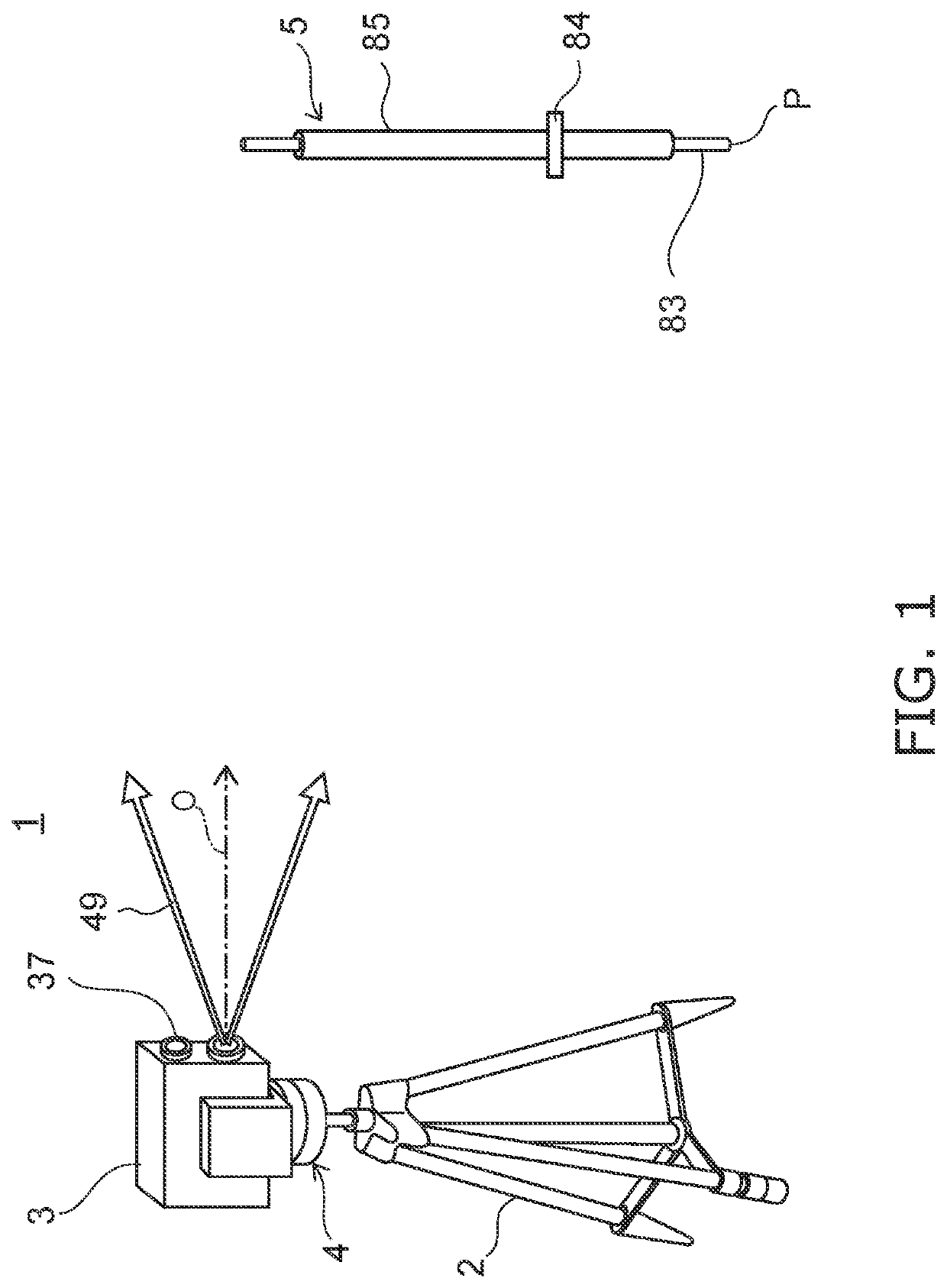
[0032]FIG. 1 is a schematic perspective view depicting a surveying system according to an embodiment of the present invention.

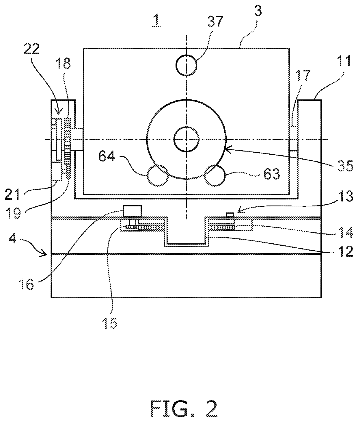
[0033]FIG. 2 is a front view depicting a surveying device main unit of the surveying system according to the present embodiment.

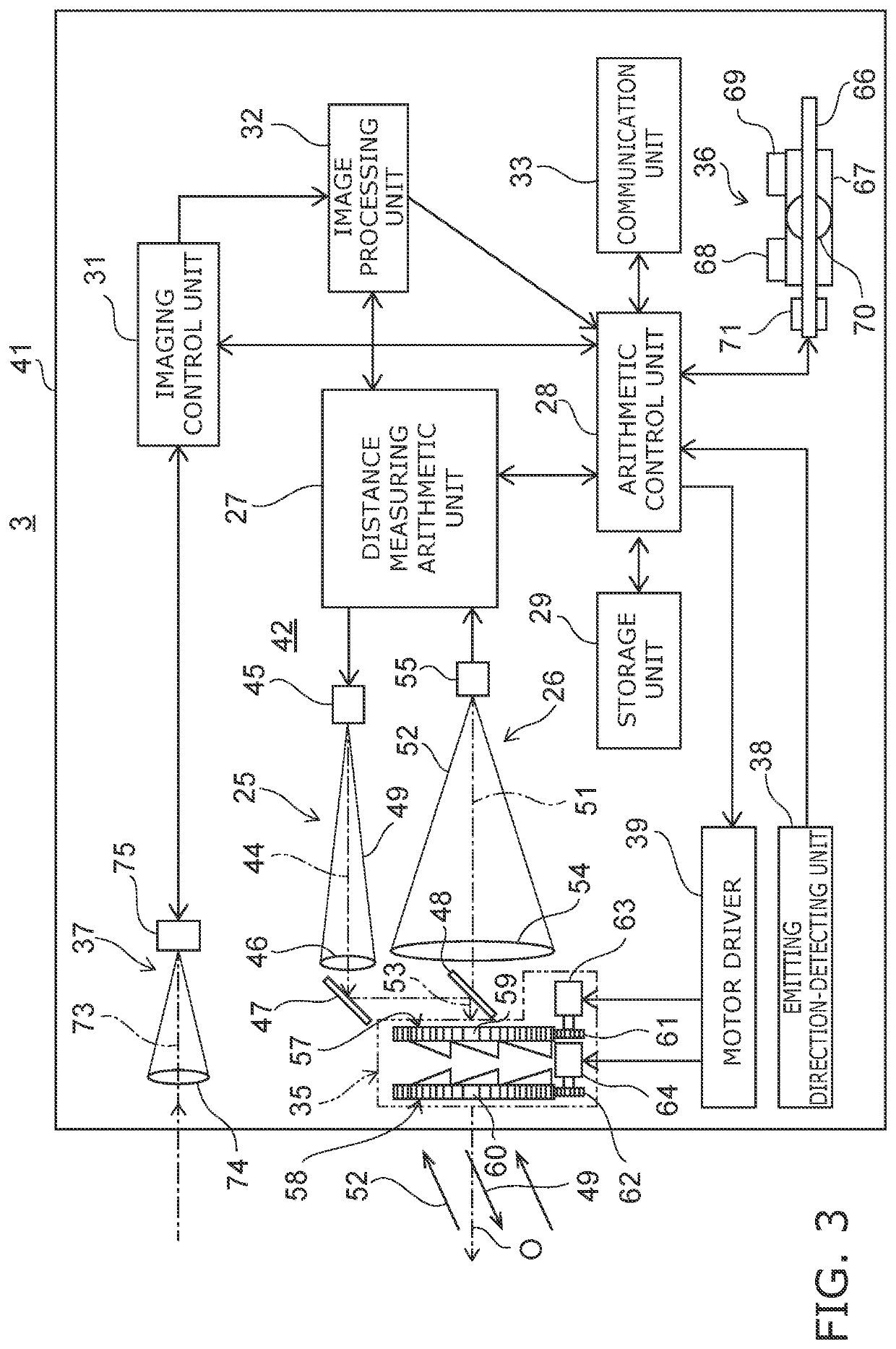
[0034]FIG. 3 is a block diagram depicting a general configuration of the surveying device main unit of the present embodiment.

[0035]The surveying system 1 according to the present ...


PUM


Abstract

The surveying device main unit includes: a distance-measuring light-emitting unit; a light-receiving unit; a distance-measuring unit; an optical axis-deflecting unit; an emitting direction-detecting unit; and an arithmetic control unit. The arithmetic control unit controls two-dimensional scanning with a scanning pattern having an intersection at which an outward passage and a return passage of the two-dimensional scanning intersect, updates three-dimensional data of the measurement target each time a light-receiving signal is detected during the two-dimensional scanning, generates weights for detecting a reference point of the measurement target and for detecting a rotation angle of the measurement target in accordance with the distance from the intersection, each time the three-dimensional data is updated, and tracks the measurement target based on the reference point position and the rotation angle of the measurement target calculated using the weights.

Description

CROSS-REFERENCE TO RELATED APPLICATIONS[0001]This application claims priority to Japanese Patent Application No. 2021-048886, filed Mar. 23, 2021, the disclosure of which is incorporated herein by reference in its entirety.FIELD OF THE INVENTION[0002]The present invention relates to a surveying system having a tracking function.BACKGROUND[0003]A total station is an example of a surveying system having a tracking function. The total station collimates a measurement target using a high magnification telescope, which also functions as a distance-measuring optical system, executes the measurement, then horizontally / vertically rotates the telescope, collimates a different measurement target and sequentially executes measurement for each measurement target. The total station also tracks movement of a measurement target and horizontally / vertically rotates the telescope accordingly, collimates the measurement target, and executes the measurement.[0004]However, in the case where the surveyin...

Claims


Application Information

Patent Timeline
IPC IPC(8): G01S7/481G01S17/14G01S17/42G01S17/66G01S7/484G02B26/10
CPCG01S7/4817G01S17/14G01S17/42G01S17/66G01S7/484G02B26/108G01S7/4972G01C15/002
Inventor MATSUMOTO, MASAE
Owner KK TOPCON
Features
  • Generate Ideas
  • Intellectual Property
  • Life Sciences
  • Materials
  • Tech Scout
  • Unparalleled Data Quality
  • Higher Quality Content
  • 60% Fewer Hallucinations
Learn More