Satellite tracking antenna system and method therefor
- Summary
- Abstract
- Description
- Claims
- Application Information
AI Technical Summary
Benefits of technology
Problems solved by technology
Method used
Image
Examples
first embodiment
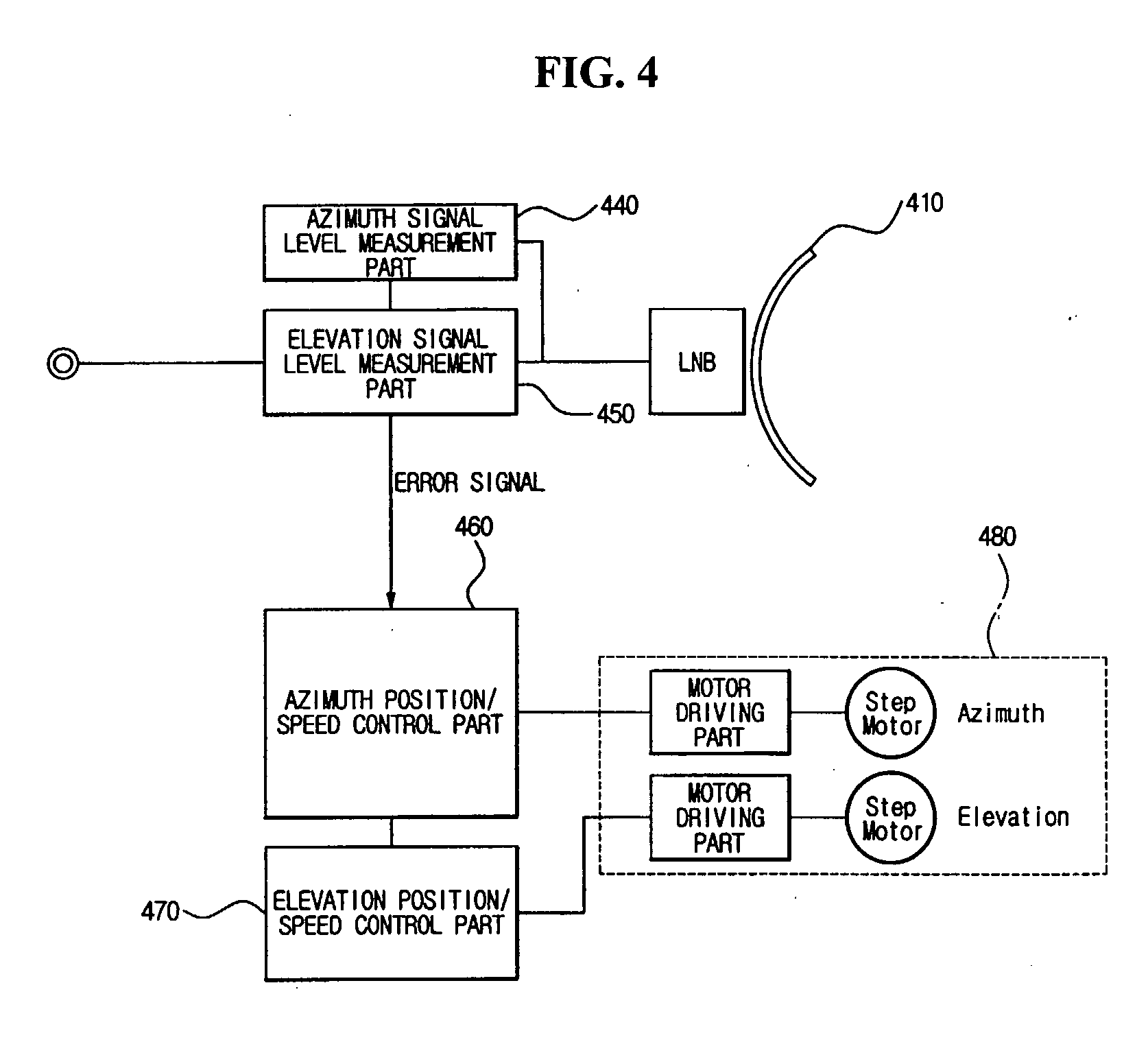
[0047]FIG. 4 is a block diagram illustrating a configuration of a satellite tracking antenna system according to the present invention.
[0048] The satellite tracking antenna system according to the first embodiment tilts a reflector in at least one specific direction to perform operation of tracking satellite signal, samples a satellite signal received in at least one position in which the reflector is tilted and disposed, generates an error signal by comparing sizes between the sampled satellite signals, and compensates a directional direction of the reflector such that the reflector is directed to a main lobe of the satellite signal.
[0049] The satellite tracking antenna system shown in FIG. 4 includes a reflector 410, an azimuth signal level measuring part 440, an elevation signal level measuring part 450, an azimuth position / speed control part 460, an elevation position / speed control part 470, and a reflector driving means 480.
[0050] The reflector 410 is directed to a satellite ...
second embodiment
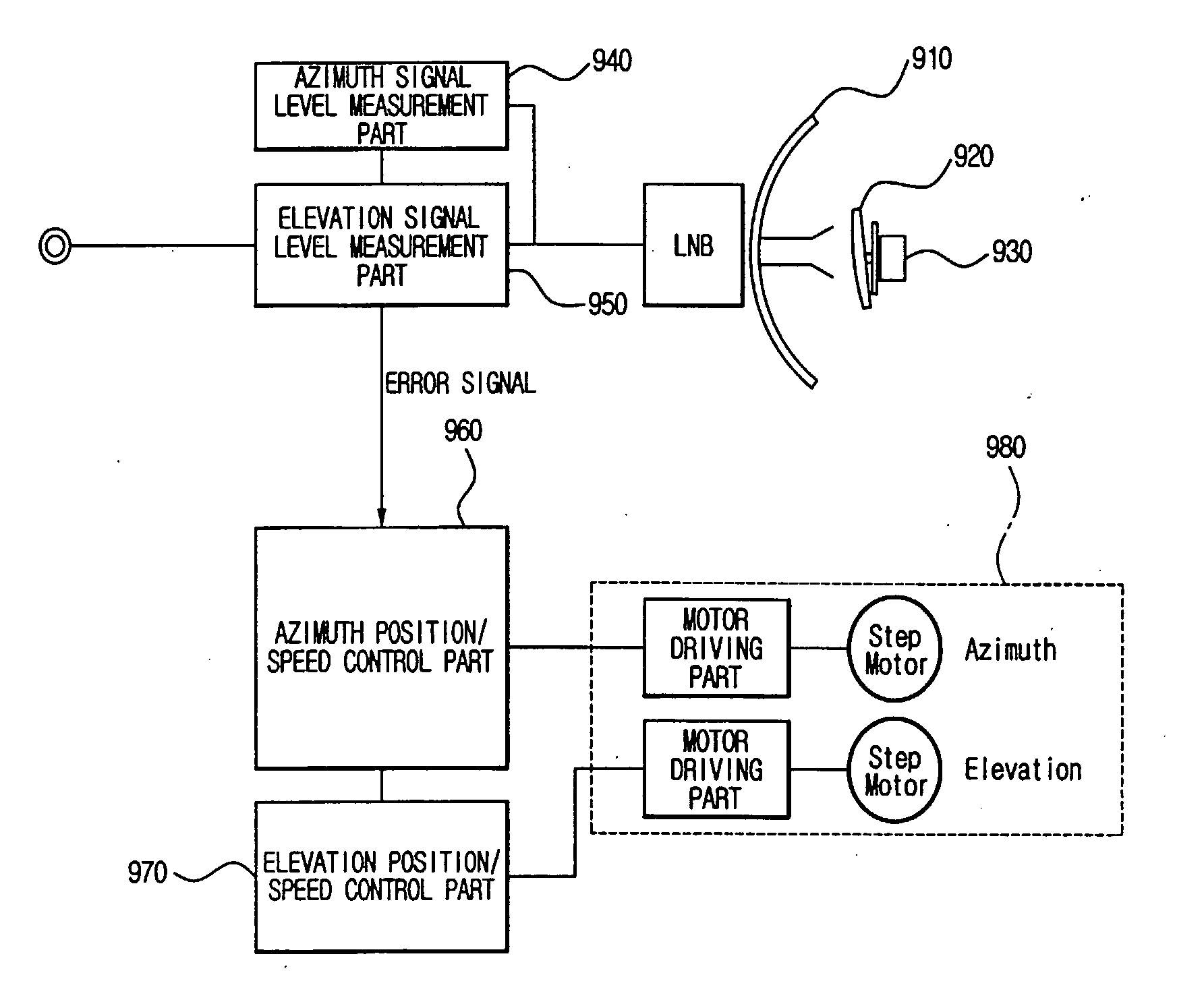
[0077]FIG. 9 is a configuration diagram illustrating a configuration of a satellite tracking antenna system according to the present invention.
[0078] The satellite tracking antenna system according to the second embodiment of the present invention illustrated in FIG. 9 includes a reflector 910, a sub-reflector 920, a sub-reflector rotation part 930, an azimuth signal level measuring part 940, an elevation signal level measuring part 950, an azimuth position / speed control part 960, an elevation position / speed control part 970, and a reflector driving means 980.
[0079] The reflector 910 is directed to a predetermined satellite and receives a satellite signal from the satellite. The reflector 910 according to the second embodiment may not perform the operation of being tilted in at least one direction as the first embodiment described above.
[0080] The sub-reflector 920 is tilted in a predetermined azimuth or elevation direction, receives the satellite signal reflected by the reflector...
third embodiment
[0096]FIG. 13 is a block diagram illustrating a configuration of a satellite tracking antenna system according to the present invention.
[0097] A conical scan tracking a satellite by rotating and tilting a sub-reflector can be applied to the satellite tracking antenna system according to the third embodiment, as the second embodiment. When the conical scan is realized, a rotation period of the sub-reflector may be changed according to aging, wear, etc. of a sub-reflector rotation part rotating the sub-reflector. The satellite tracking antenna system according to the third embodiment compensates a satellite signal sampling period in response to rotation period change of the sub-reflector.
[0098] As illustrated in FIG. 13, the satellite tracking antenna system includes a reflector 1310, a sub-reflector 1320, a sub-reflector rotation part 1330, a satellite signal sampling part 1340, a period control module 1350, an azimuth position / speed control part 1360, an elevation position / speed co...
PUM
 Abstract
Description
Claims
Application Information
 - R&D
- Intellectual Property
- Life Sciences
- Materials
- Tech Scout
- Unparalleled Data Quality
- Higher Quality Content
- 60% Fewer Hallucinations
Browse by: Latest US Patents, China's latest patents, Technical Efficacy Thesaurus, Application Domain, Technology Topic, Popular Technical Reports.
© 2025 PatSnap. All rights reserved.Legal|Privacy policy|Modern Slavery Act Transparency Statement|Sitemap|About US| Contact US: help@patsnap.com


