Image processing apparatus, image processing method, and computer-readable storage device

a technology of image processing apparatus and contour edge, which is applied in the field of image processing apparatus and image processing method, and the detection of contour edge by computer-readable storage device, can solve the problems of inability to detect difficulty in appropriately distinguishing edges that need to be connected from noise edges, and discontinuation of contour edges

Inactive Publication Date: 2012-03-29
OLYMPUS CORP
View PDF2 Cites 29 Cited by
  • Summary
  • Abstract
  • Description
  • Claims
  • Application Information

AI Technical Summary

Benefits of technology

[0010]The above and other features, advantages and technical and industrial significance of this invention will be better understood by reading the following detailed description of presently preferred embodiments of the invention, when considered in connection with the accompanying drawings.

Problems solved by technology

When contour edges are detected from an image by using the above edge detection method, the contour edges may be discontinued due to various causes, such as the degree of precision of an edge detection algorithm, noise, or an unclear image (blurring), or due to a subjective contour portion.
However, in the technique using the conventional active contour method, there is a problem in that it is difficult to appropriately discriminate edges that need to be connected from noise edges.
Thus, the edge tracing method is dependent on local information and therefore is disadvantageous to noise, so that edges that need to be connected may not be detected in some cases.

Method used


Image

  • Image processing apparatus, image processing method, and computer-readable storage device
  • Image processing apparatus, image processing method, and computer-readable storage device
  • Image processing apparatus, image processing method, and computer-readable storage device

Examples


first embodiment

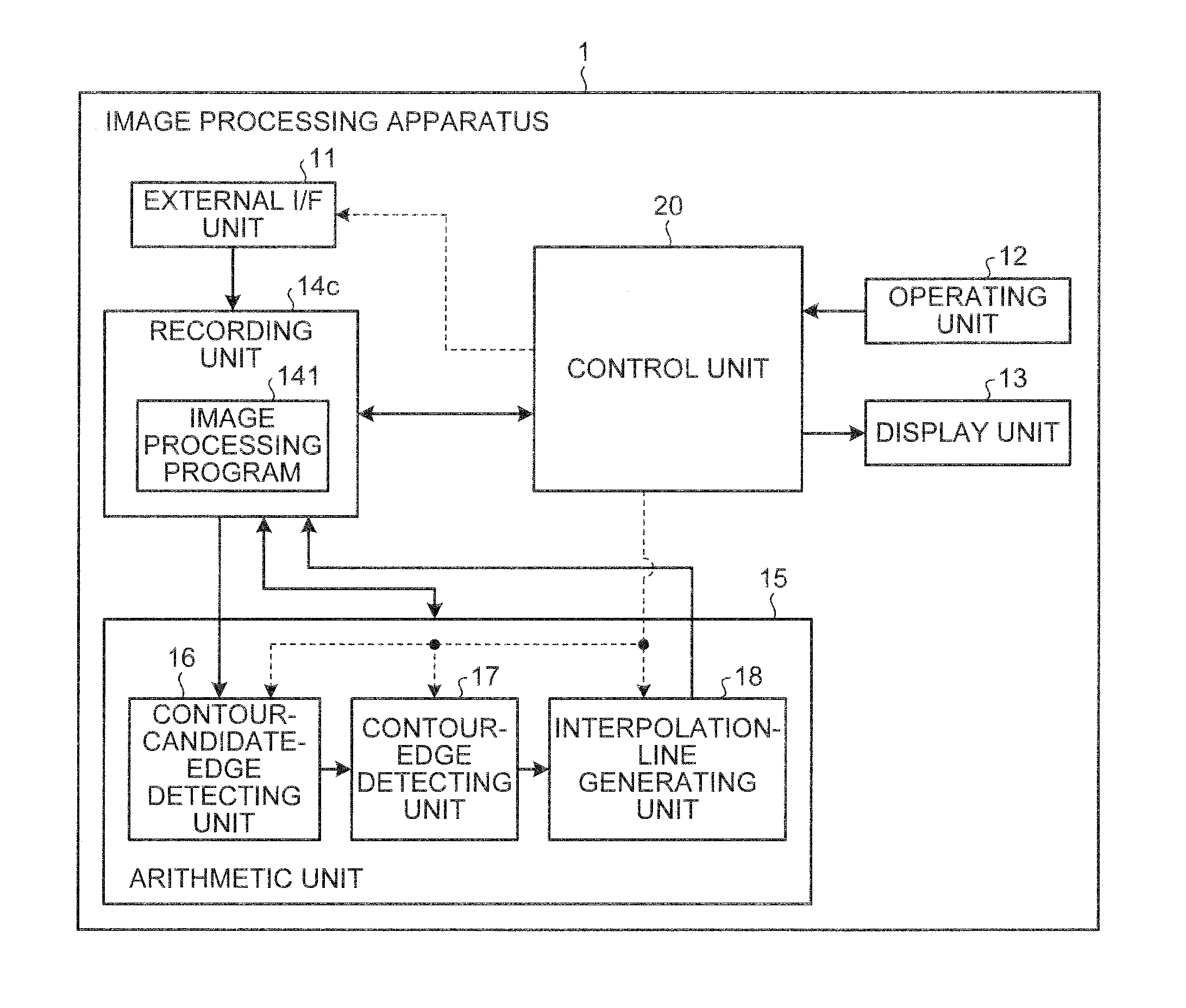
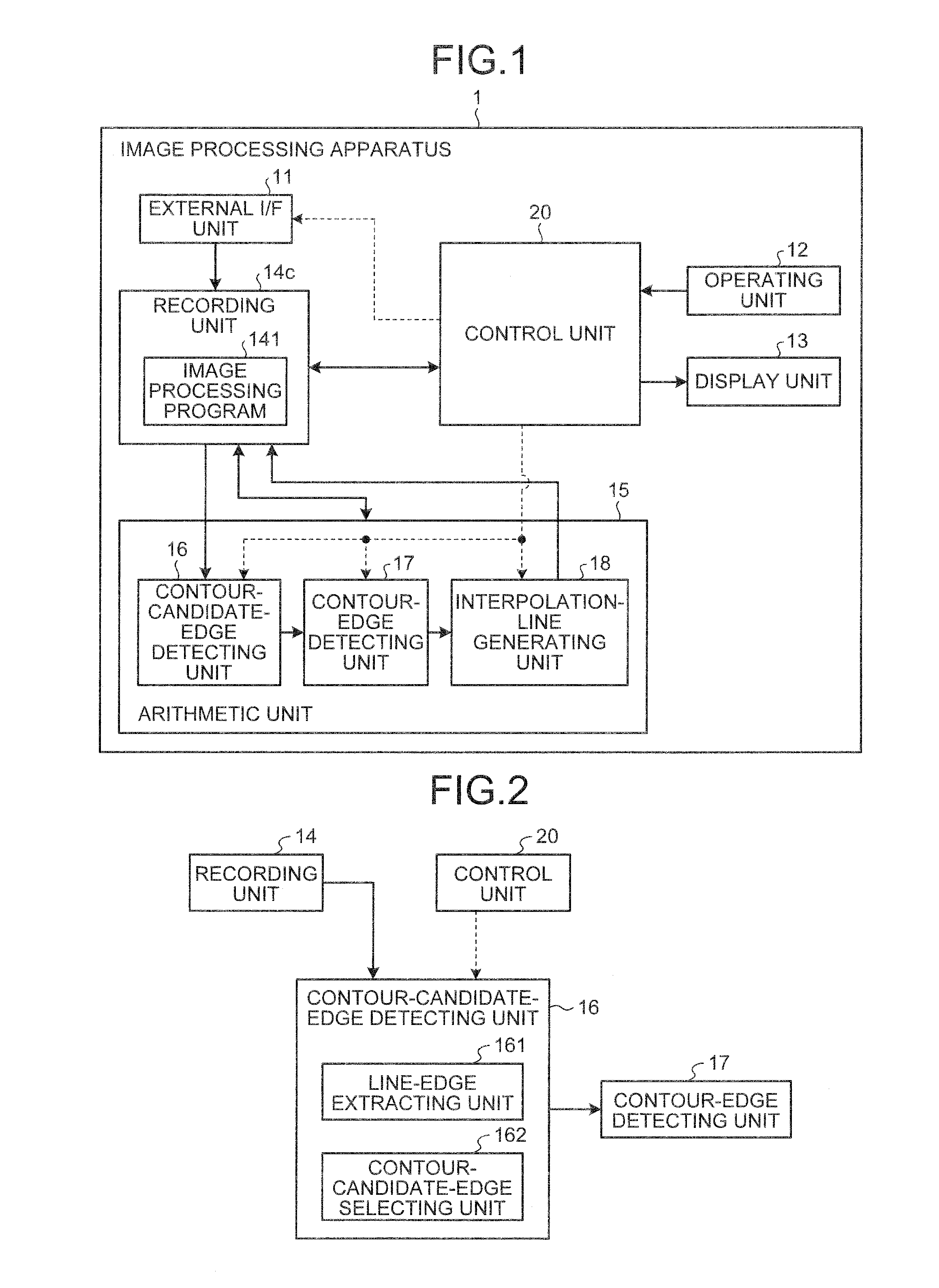
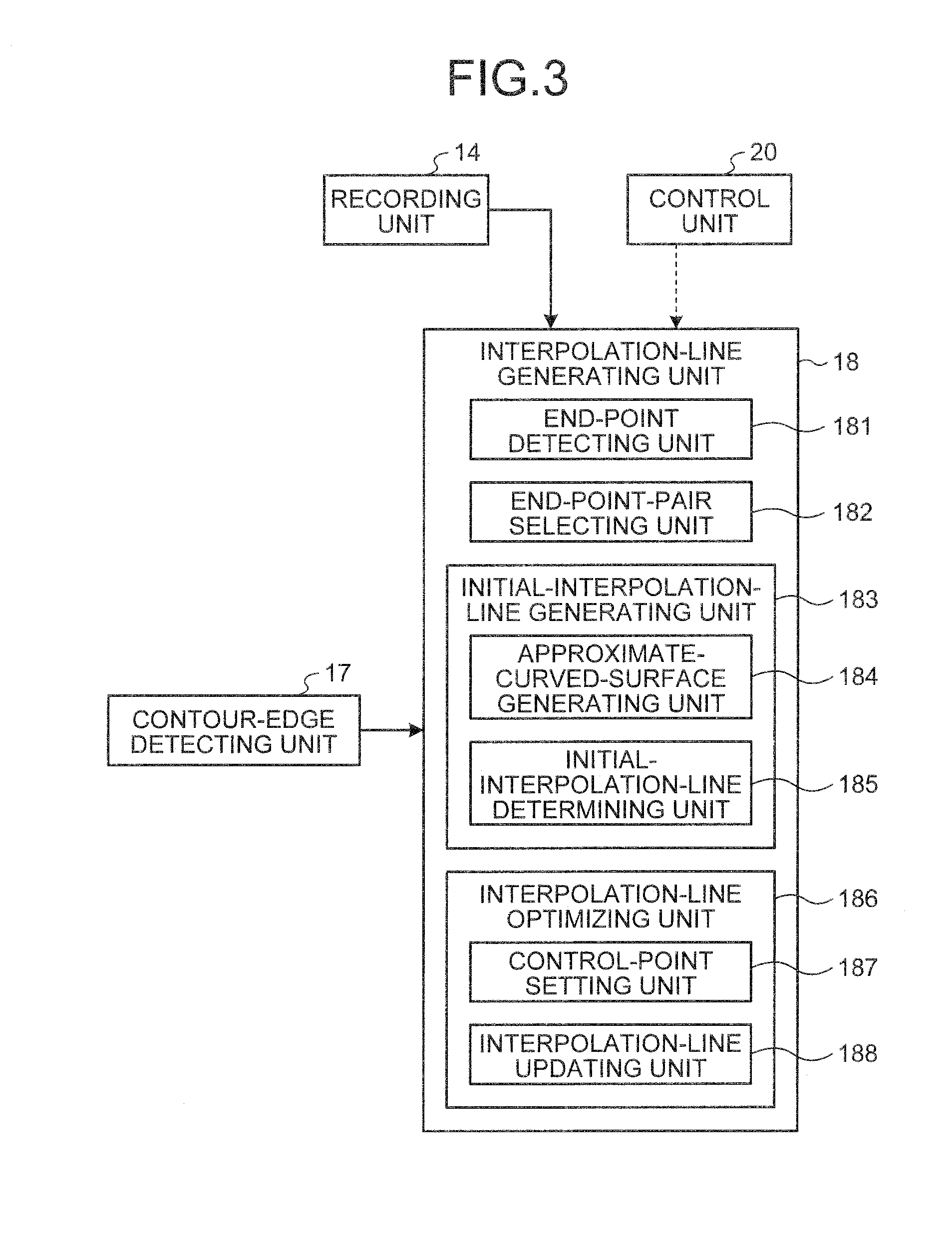
[0038]An image processing apparatus according to a first embodiment will be described below. FIG. 1 is a block diagram of a functional configuration example of an image processing apparatus 1 according to the first embodiment. FIG. 2 is a block diagram of a configuration example of a contour-candidate-edge detecting unit 16 according to the first embodiment. FIG. 3 is a block diagram of a configuration example of an interpolation-line generating unit 18 according to the first embodiment. In FIGS. 1 to 3, data signal lines used for connecting the units of the image processing apparatus 1 to one another and sending data signals, such as image signals, are indicated by bold lines and control signal lines used for sending control signals are indicated by dashed lines.

[0039]As illustrated in FIG. 1, the image processing apparatus 1 of the first embodiment includes an external interface (I / F) unit 11, an operating unit 12, a display unit 13, a recording unit 14, an arithmetic unit 15, and...

first modification

[0101]FIG. 16 is a block diagram of a configuration example of a contour-candidate-edge detecting unit 16a according to a first modification of the first embodiment. An image processing apparatus of the first modification can be constructed by replacing the contour-candidate-edge detecting unit 16 of FIG. 1 with the contour-candidate-edge detecting unit 16a of FIG. 16. In FIG. 16, the same components as those of the first embodiment are denoted by the same reference codes. As illustrated in FIG. 16, according to the first modification, the contour-candidate-edge detecting unit 16a includes the line-edge extracting unit 161, a branched-edge removing unit 163a, and the contour-candidate-edge selecting unit 162.

[0102]The branched-edge removing unit 163a removes line edge portions branched from a line edge extracted by the line-edge extracting unit 161. According to the first modification, the contour-candidate-edge selecting unit 162 selects an edge portion formed of pixels that are co...

second modification

[0105]FIG. 19 is a block diagram of a configuration example of an interpolation-line generating unit 18b according to a second modification of the first embodiment. An image processing apparatus of the second modification can be realized by replacing the interpolation-line generating unit 18 of FIG. 1 with the interpolation-line generating unit 18b of FIG. 19. In FIG. 19, the same components as those of the first embodiment are denoted by the same reference codes. As illustrated in FIG. 19, according to the second modification, the interpolation-line generating unit 18b includes the end-point detecting unit 181, the end-point-pair selecting unit 182, the initial-interpolation-line generating unit 183, and an interpolation-line optimizing unit 186b. According to the second modification, the interpolation-line optimizing unit 186b includes a path searching unit 189b.

[0106]The second modification is different from the first embodiment in that path search processing is performed instea...


PUM


Abstract

An image processing apparatus includes a contour-candidate-edge detecting unit that detects, as contour candidate edges, edges based on a gradient magnitude of each pixel in a target image; a contour-edge detecting unit that detect contour edges by performing thresholding on gradient magnitudes of the contour candidate edges; an interpolation-line generating unit that generates interpolation lines for connecting end points of respective end-point pairs based on gradients of pixel values between the end points while each of the end point pairs is made up of an end point of an identical contour edge as a connection base and an end point of a different contour edge as a connection destination; and a contour-edge interpolating unit that selects one of the interpolation lines based on the gradients of pixel values on the interpolation lines and interpolates a contour edge between the end points with the selected interpolation line.

Description

CROSS-REFERENCE TO RELATED APPLICATIONS[0001]This application is based upon and claims the benefit of priority from Japanese Patent Application No. 2010-219801, filed on Sep. 29, 2010, the entire contents of which are incorporated herein by reference.BACKGROUND OF THE INVENTION[0002]1. Field of the Invention[0003]The present invention relates to an image processing apparatus, an image processing method, and a computer-readable storage device for detecting a contour edge from a target image.[0004]2. Description of the Related Art[0005]In general, an edge in an image is detected by detecting a position at which a change in a gradient is the greatest (a position at which a gradient is steep and a value of the gradient is greater than those of adjacent positions). Basically, edges are detected by calculating gradient magnitudes from gradients of luminance values in an image and performing thresholding on the gradient magnitudes. When contour edges are detected from an image by using the...

Claims


Application Information

Patent Timeline
Patent Type & Authority Applications(United States)
IPC IPC(8): G06K9/48
CPCH04N5/142G06T7/0085G06T2207/30092G06T2207/20136G06T2207/30028G06T2207/10068G06T7/13G06T7/181
Inventor KONO, TAKASHIKANDA, YAMATOKITAMURA, MAKOTOMATSUDA, TAKEHIROHIROTA, MASASHI
Owner OLYMPUS CORP
Why Eureka
Try Eureka