
Exercise apparatus

a technology of exercise apparatus and apparatus, applied in the field of exercise apparatus and method of exercise, can solve the problems of inability to easily regulate the resistance of hydraulic resistance systems, the size and weight of hydraulic resistance systems are usually large, and the device is usually heavy, so as to increase the mechanical advantage and the constant resistance of movement

Inactive Publication Date: 2012-03-29
DEDOV VADIM
View PDF2 Cites 16 Cited by
  • Summary
  • Abstract
  • Description
  • Claims
  • Application Information

AI Technical Summary

Benefits of technology

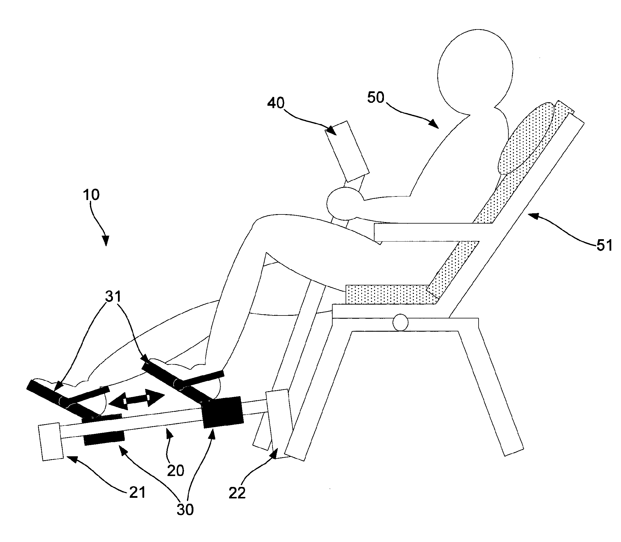
[0053]Typically the apparatus includes a docking member removably mounted to the frame, the docking member being for engaging a user support to thereby stabilising the apparatus in use.
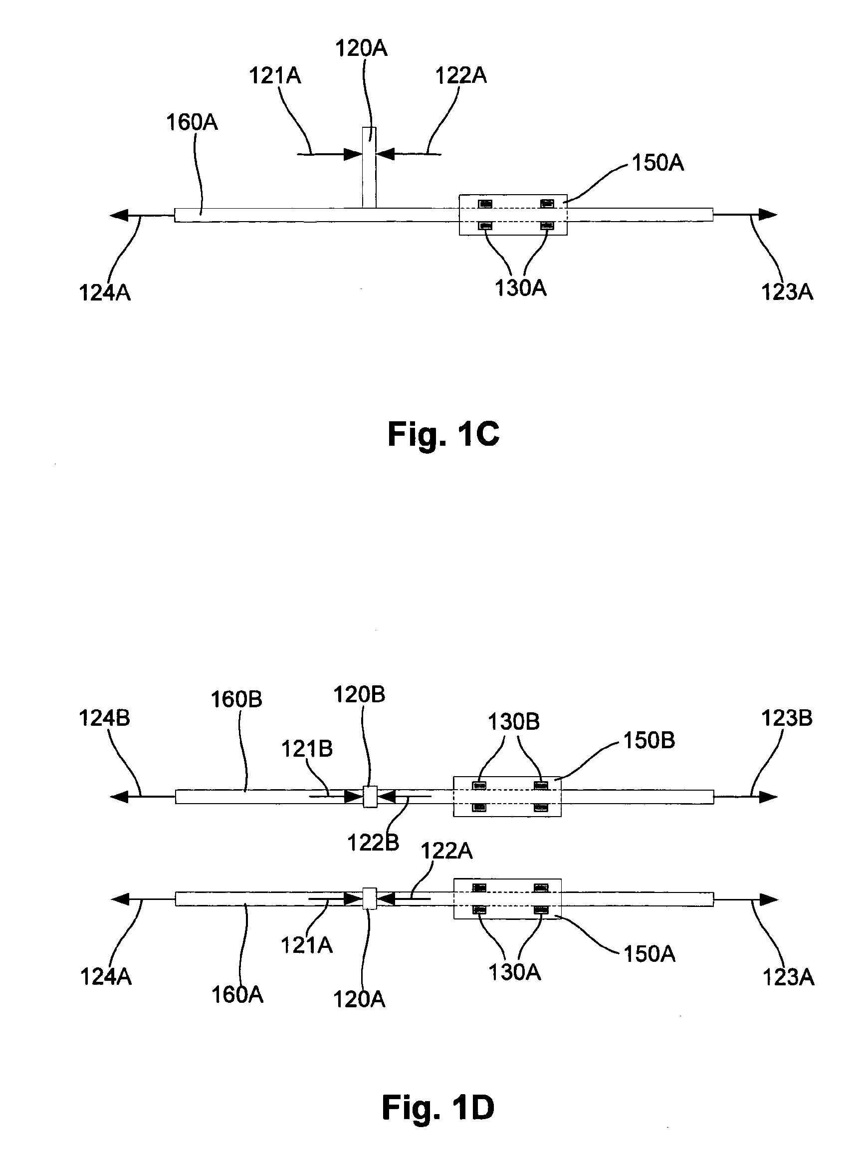
[0076]Typically each sliding brake comprise aperture corresponding to the cross-section of the guide rail; wherein the slide member is mounted onto the guide rail so that the guide rail goes to through the sliding brakes inside the tube of the slide member; wherein sliding brakes are positioned in succession on the guide rail; wherein corresponding cross-sections of holes in the brakes and tubes of the guide rail ensures side-wise stability of the slide member.
[0078]Typically the apparatus includes means to transfer user's muscle force into tension between sliding brakes and guide rail via lever mechanism, resulting in friction between brakes and guide rail and, therefore, frictional resistance to user's efforts, whereas sliding properties of brakes allow smooth resisted skidding of the slide member along the guide rail, allowing exercising of user's muscles.
[0080]Typically the tube of the slide member includes at least two slots and respective bolts with nuts for at least one sliding brake, allowing changing position of at least one sliding brake inside the tube along the slots, allowing varying the distance between brakes; wherein the shorter distance between brakes results in jamming action between brakes and the guide rail, and resultant higher constant resistance to movement of slide member along the guide rail in both directions and vice verse; wherein the shorter distance between brakes increases mechanical advantage in the lever action during exercise stroke due shorter load arm of the lever and vice verse.

Problems solved by technology

These devices are usually heavy, bulky and expensive that is, at least in part, due to complex brake systems used in these devices.
Hydraulic resistance systems have considerable size and weight, and their resistance cannot be easily regulated.
Weight based equipment utilises force of gravity but is awkward and unsafe to use without supervision.
These properties of existing resistance systems significantly limit design of new exercise devices and new applications of existing exercise devices.
For example, existing miniature exercise devices, e.g. mini steppers and bikes, have significantly limited capabilities and are awkward to use, where miniaturization results in short distance of resisted movement (working distance).
Short working distance makes exercises confined only to small muscle groups and, therefore, not efficient.
Even standard bicycles do not provide resistance for full range of human leg extension, allowing only about 30 cm of resisted movement.
In addition, all bicycle-like devices have non-linear trajectory of resisted movements due to platform revolution and no resistance for leg flexion, e.g. no hamstring muscles load.
Other limitations of existing exercise devices are non-physiological resistance profiles, rigid regulation of resistance and non-linear trajectory of resistance movements.
Such devices do not allow the user to work at his or her maximum capabilities during that portion of movement in which the user has higher strength capabilities because muscle torque is maximal in the middle of contraction and drops towards the full muscle contraction.

Method used


Image

  • Exercise apparatus
  • Exercise apparatus
  • Exercise apparatus

Examples


Embodiment Construction

[0115]The following description of the preferred embodiments is merely exemplary in nature and is in no way intended to limit the invention, its application, or uses.

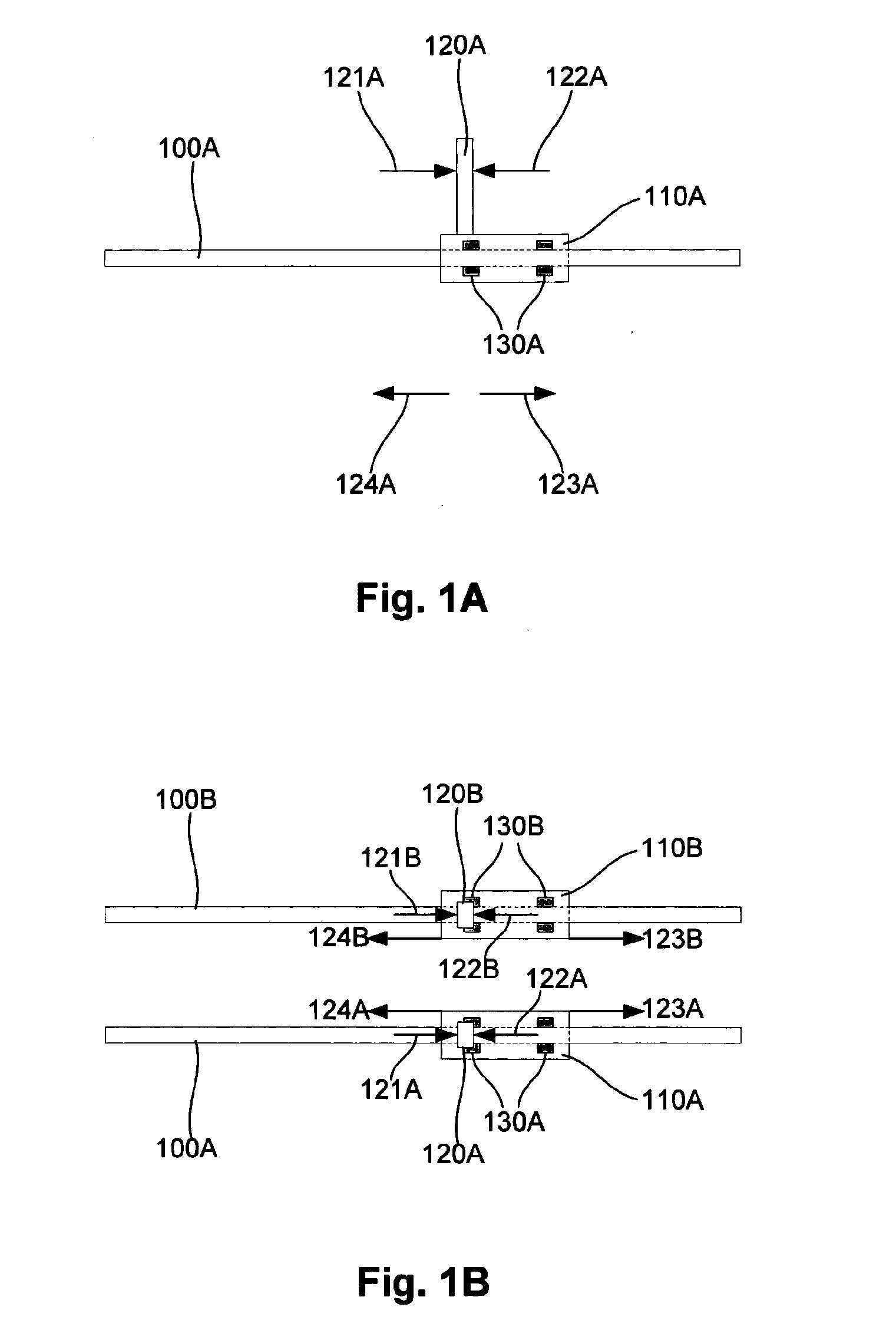
[0116]An example of exercise apparatus will now be described with reference to FIGS. 1A and 1B.

[0117]In this example, the exercise apparatus includes two guides 100A, 100B, each having a respective sliding member 110A, 110B slidably mounted thereon. Each sliding member 110A, 110B includes an operating member 120A, 120B for allowing a user to apply first and second operating forces 121A, 122A; 121B, 122B to the sliding member 120A, 120B to thereby selectively slide the sliding member 120A, 120B in respective first and second directions 123A, 124A; 123B, 124B.

[0118]Each sliding member 110A, 110E also includes a resistance mechanism, 130 for generating respective first and second resistive forces when the sliding member is moved in the first and second directions.

[0119]Typically the operating member 120A, 120B is in the fo...


PUM


Abstract

Exercise apparatus including a guide and a sliding member slidably mounted to the guide, the sliding member including an operating member for allowing a user to apply first and second operating forces to the sliding member to thereby selectively slide the sliding member in respective first and second directions and a resistance mechanism for generating respective first and second resistive forces when the sliding member is moved in the first and second directions.

Description

BACKGROUND OF THE INVENTION[0001]The present invention relates to an exercise apparatus and method of exercising using an exercise apparatus, and more particularly to exercise apparatus for providing variable resistance to movement.DESCRIPTION OF THE PRIOR ART[0002]The reference in this specification to any prior publication (or information derived from it), or to any matter which is known, is not, and should not be taken as an acknowledgment or admission or any form of suggestion that the prior publication (or information derived from it) or known matter forms part of the common general knowledge in the field of endeavour to which this specification relates.[0003]Numerous health benefits of exercises resulted in popularity of exercise devices, which can be used at use's convenience, including in private homes and specialised gyms. Most common types of resistance exercise equipment include upright and recumbent bikes, elliptical trainers, rowers, steppers and strength equipment. The...

Claims


Application Information

Patent Timeline
Patent Type & Authority Applications(United States)
IPC IPC(8): A63B71/00
CPCA47C9/002A63B2220/17A63B22/0012A63B22/0046A63B22/0076A63B22/203A63B22/205A63B23/03541A63B23/0355A63B23/03575A63B23/0405A63B23/0494A63B23/12A63B2021/1609A63B2022/0038A63B2022/0041A63B2022/206A63B2208/0204A63B2208/0233A63B2210/50A63B22/0007A63B21/1609A63B23/1209A63B23/1263A63B21/4035A63B21/4015A63B21/4045A63B21/4033A63B21/4047
Inventor DEDOV, VADIM
Owner DEDOV VADIM
Learn More