An expanded-diameter extrusion friction anchor rod and anchor cable structure

An anchor rod and anchor cable technology, which is used in the installation of anchor rods, infrastructure engineering, construction, etc., can solve the problems of damaged anchor rod work performance, constant resistance instability, poor impact resistance, etc., and achieves easy design, processing and production. On-site installation, stable structure with constant resistance and strong impact resistance

Active Publication Date: 2020-03-17
LIAONING TECHNICAL UNIVERSITY
View PDF3 Cites 0 Cited by
  • Summary
  • Abstract
  • Description
  • Claims
  • Application Information

AI Technical Summary

Problems solved by technology

The Chinese patent No. 201710556137.9 discloses a squeeze-friction constant-resistance yielding large-deformation bolt, which provides constant resistance to the extrusion friction of the casing through steel balls, but the contact between the steel ball and the casing is a point-line contact. The contact area is small, so the constant resistance generated is small, and the steel ball is not an integral component. When a single or multiple steel balls are damaged, it will cause uneven force on the rod body, damage the working performance of the anchor rod, and easily cause instability and damage.
[0004] In short, the existing conventional bolts have low elongation and poor impact resistance, which is difficult to meet the engineering requirements, and the existing large deformation energy-absorbing bolts are unstable in constant resistance or prone to structural instability due to their respective principles and structural defects. , the effect is not ideal

Method used


Image

  • An expanded-diameter extrusion friction anchor rod and anchor cable structure
  • An expanded-diameter extrusion friction anchor rod and anchor cable structure
  • An expanded-diameter extrusion friction anchor rod and anchor cable structure

Examples


Embodiment 1

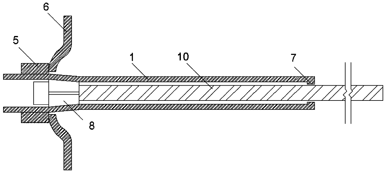
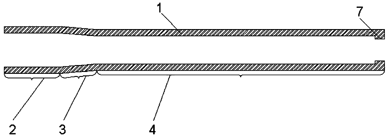
[0034] Such as Figure 1 ~ Figure 3 and Figure 4-1 to Figure 4-3 As shown, a diameter-expanding extruded friction anchor structure is an external type, including a casing 1, and the casing 1 includes a large-diameter area 2, an enlarged-diameter area 3, and a small-diameter area 4 , the outer wall of the large diameter area 2 of the casing 1 is screwed with a nut 5, the nut 5 is set as a high-strength nut, and the end of the nut 5 close to the expansion area 3 of the casing 1 is provided with a tray 6, and the tray 6 is set as a metal butterfly As for the tray, a stopper 7 is provided at the end of the small diameter area 4 of the casing 1 away from the expansion area 3, and the stopper 7 and the small diameter area 4 are integrally formed or the stopper 7 is screwed to the small diameter area 4, and the stopper The installation method of 7 and small diameter area 4 can be selected according to the specific construction requirements, and the inner diameter of the through hol...

Embodiment 2

[0036] Such as Figure 5 and Figure 6-1 to Figure 6-3 As shown, a diameter-expanding extruded friction anchor cable structure is external, including a casing 1, and the casing 1 includes a large-diameter area 2, an enlarged-diameter area 3, and a small-diameter area 4 , the outer wall of the large diameter area 2 of the casing 1 is screwed with a nut 5, the nut 5 is set as a high-strength nut, and the end of the nut 5 close to the expansion area 3 of the casing 1 is provided with a tray 6, and the tray 6 is set as a metal butterfly As for the tray, a stopper 7 is provided at the end of the small diameter area 4 of the casing 1 away from the expansion area 3, and the stopper 7 and the small diameter area 4 are integrally formed or the stopper 7 is screwed to the small diameter area 4, and the stopper The installation method of 7 and small diameter area 4 can be selected according to specific construction requirements, and the inner diameter of the through hole of the stopper 7 ...

Embodiment 3

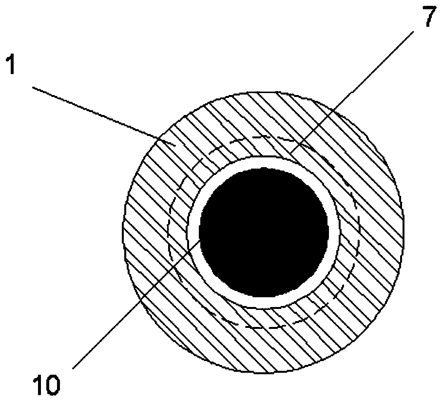
[0038] Such as Figure 7 and Figure 8 As shown, a diameter-expanding extruded friction anchor structure is built-in, and includes a sleeve 1, and the sleeve 1 includes a large-diameter area 2, an enlarged-diameter area 3, and a small-diameter area 4, The small diameter area 4 of the casing 1 is provided with a limiter 7 in the inner hole at one end away from the enlarged diameter area 3, and the limiter 7 and the small diameter area 4 are integrally formed or the limiter 7 is screwed with the small diameter area 4, and the limiter The installation method of 7 and small diameter area 4 can be selected according to the specific construction requirements, and the inner diameter of the through hole of the stopper 7 is larger than the outer diameter of the rod body 10, and the stopper 7 can be limited after the bolt expander 8 reaches the maximum slippage. Its displacement continues to exert the mechanical properties of the rod body 10 and the casing 1 itself. The large diameter ...


PUM


Abstract

An expanding extrusion friction anchor rod / anchor cable structure belongs to the technical field of coal and rock mass power supply and soft rock support and includes a sleeve, a large diameter area,an expanding area, a small diameter area, a nut, a tray, a limiting stopper, a rod body, a cable body, a straight groove, a clamp, a guide groove and an anchor. According to the invention, a constantresistance is generated through expanding extrusion and friction between an anchor rod tube expander or an anchor cable tube expander, and a deformation volume is provided for relative slippage of theanchor rod tube expander or the anchor cable tube expander, so that a specific high support constant resistance is provided for a supported surrounding rock so as to make the supported surrounding rock always in a three-direction stressed state and thus to form an annular support pressure arch with a comparatively large thickness. Also, a specific amount of deformation energy and impact energy can be absorbed through axial slippage of the expanding extrusion friction rod / cable structure and the associated deformation of the supported surrounding rock. Finally, effects of constant resistancesupport and relief energy absorption support are achieved and the stability of the supported surrounding rock is ensured in the maximal level.

Description

technical field [0001] The invention belongs to the technical field of coal rock mass dynamic support and soft rock support, and in particular relates to a diameter-expanding extrusion friction bolt and anchor cable structure. Background technique [0002] In coal mines, metal mines, water conservancy, tunnels and other geotechnical engineering, bolts are efficient and widely used active support components. However, with the development of our country's economy, the scale of the project continues to expand, and the geological conditions it faces are becoming more and more complex. In shallow rock mass engineering, under the action of external factors such as earthquakes, human disturbance, water, or internal factors such as rock mass self-expansion, the rock mass loses its bearing capacity, and disasters such as large deformation, landslides, and landslides occur; The rock mass under the stress state is prone to disasters such as large deformation of soft rocks. At the same...

Claims


Application Information

Patent Timeline
Patent Type & Authority Patents(China)
IPC IPC(8): E21D21/00E02D5/74
CPCE02D5/74E21D21/0073
Inventor 赵宝友李佳伟张立新王爱文郑天照
Owner LIAONING TECHNICAL UNIVERSITY
Why Eureka
Try Eureka