
Systems and methods for providing quality of service via a flow controlled tunnel

a flow control and quality management technology, applied in the field of data communication networks, can solve the problems of complicated quality of service management, undesirable, and difficult per-link configuration, and achieve the effect of easy balanced and prioritized

Active Publication Date: 2012-03-29
CITRIX SYST INC
View PDF14 Cites 99 Cited by
  • Summary
  • Abstract
  • Description
  • Claims
  • Application Information

AI Technical Summary

Benefits of technology

[0003]The present invention is directed towards systems and methods for providing Quality of Service (QoS) via a flow controlled tunnel. Traffic from a plurality of applications may be directed into a single connection or flow-controlled tunnel and QoS policies may be applied across the plurality of applications without configuration of individual link speeds, enabling QoS scheduling to dynamically adjust traffic transmission and reception rates to ensure priority management of applications regardless of a final endpoint of the application communications. Accordingly, traffic of different types, including VPN, HTTP, Voice-over-IP (VoIP), remote desktop protocol traffic, or other traffic may be easily balanced and prioritized. In many embodiments, the tunnel may be transparent to applications, such that without any application configuration, application traffic may still be prioritized by QoS requirements.

Problems solved by technology

However, because of the different demands of these applications, and different server or endpoint destinations for application traffic, quality of service management may be complicated or require tedious per-link configuration.
This may be particularly undesirable in mobile environments, such as smartphones or laptops, where users may connect from several different locations and over several different links in a week, or even in a single day.

Method used


Image

  • Systems and methods for providing quality of service via a flow controlled tunnel
  • Systems and methods for providing quality of service via a flow controlled tunnel
  • Systems and methods for providing quality of service via a flow controlled tunnel

Examples


Embodiment Construction

[0029]For purposes of reading the description of the various embodiments of the present invention below, the following descriptions of the sections of the specification and their respective contents may be helpful:[0030]Section A describes a network environment and computing environment useful for practicing an embodiment of the present invention;[0031]Section B describes embodiments of a system and appliance architecture for accelerating delivery of a computing environment to a remote user;[0032]Section C describes embodiments of a client agent for accelerating communications between a client and a server; and[0033]Section D describes embodiments of systems and methods for classifying network packets.

A. Network and Computing Environment

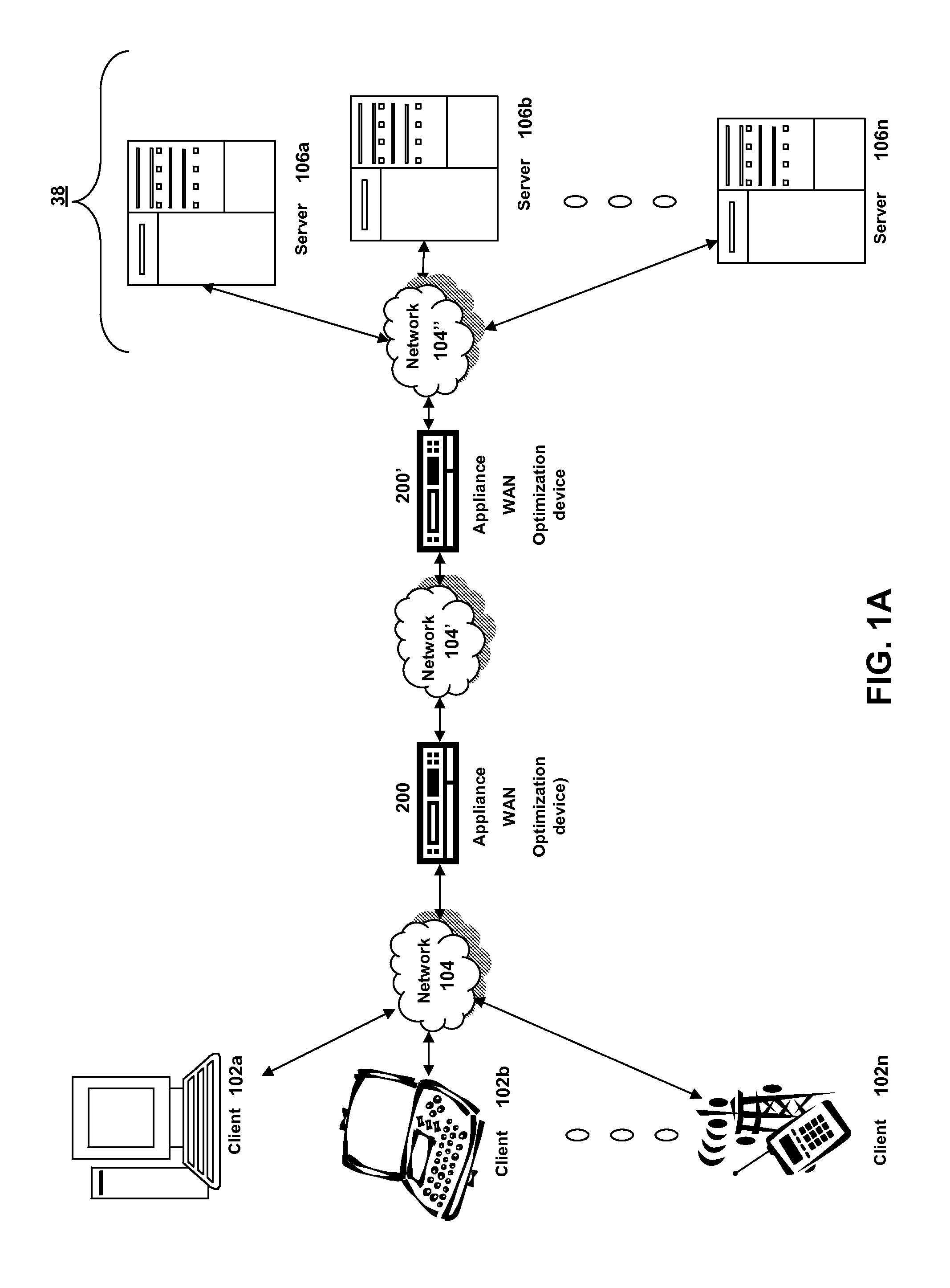
[0034]Prior to discussing the specifics of embodiments of the systems and methods of an appliance and / or client, it may be helpful to discuss the network and computing environments in which such embodiments may be deployed. Referring now to FIG. 1A, ...


PUM


Abstract

The present invention is directed towards systems and methods for providing Quality of Service (QoS) via a flow controlled tunnel. Traffic from a plurality of applications may be directed into a single connection or flow-controlled tunnel and QoS policies may be applied across the plurality of applications without configuration of individual link speeds, enabling QoS scheduling to dynamically adjust traffic transmission and reception rates to ensure priority management of applications regardless of a final endpoint of the application communications. Accordingly, traffic of different types, including VPN, HTTP, Voice-over-IP (VoIP), remote desktop protocol traffic, or other traffic may be easily balanced and prioritized. In many embodiments, the tunnel may be transparent to applications, such that without any application configuration, application traffic may still be prioritized by QoS requirements.

Description

FIELD OF THE INVENTION[0001]The present disclosure generally relates to data communication networks. In particular, the present disclosure relates to systems and methods for providing quality of service of a plurality of applications via a flow controlled tunnel.BACKGROUND OF THE INVENTION[0002]In many systems executing a plurality of applications, it may be desirable to prioritize communications among the applications to meet performance, bandwidth and latency requirements. However, because of the different demands of these applications, and different server or endpoint destinations for application traffic, quality of service management may be complicated or require tedious per-link configuration. This may be particularly undesirable in mobile environments, such as smartphones or laptops, where users may connect from several different locations and over several different links in a week, or even in a single day.BRIEF SUMMARY OF THE INVENTION[0003]The present invention is directed t...

Claims


Application Information

Patent Timeline
IPC IPC(8): G06F15/16H04L47/6275H04L47/80
CPCH04L47/19H04L47/24H04L47/6275H04L67/10H04L47/825H04L65/80H04L47/803
Inventor JACKOWSKI, STEVEKEITH, SETHTESTICIOGLU, KUTLUK
Owner CITRIX SYST INC
Learn More