
Speed regulation method and device

a technology of speed regulation and speed control, applied in the direction of mechanical control devices, controlling members, limiting/preventing/returning movement of parts, etc., can solve problems such as hysteresis effects, and achieve the effect of not affecting the actuation capability of electric motors

Inactive Publication Date: 2012-04-05
CONTI TEMIC MICROELECTRONIC GMBH
View PDF12 Cites 8 Cited by
  • Summary
  • Abstract
  • Description
  • Claims
  • Application Information

AI Technical Summary

Benefits of technology

[0020]The device according to aspects of the invention for regulating the speed of a motor vehicle describes a compact pedal system for use in a motor vehicle having a housing and having a force resetting device which is integrated to the housing. The resetting force on the pedal lever in the direction of the zero position thereof is generated, in particular, by energizing an electric motor. The electric motor comprises a stator and a rotor which is arranged on a shaft. In addition, a drive pulley is arranged on the shaft of the electric motor, which drive pulley can apply the resetting force to the pedal lever by

Problems solved by technology

In a pedal characteristic curve, the forward movement characteristic curve, which corresponds to the profile of the opposing force as the pedal angle increases i

Method used


Image

  • Speed regulation method and device
  • Speed regulation method and device
  • Speed regulation method and device

Examples


Embodiment Construction

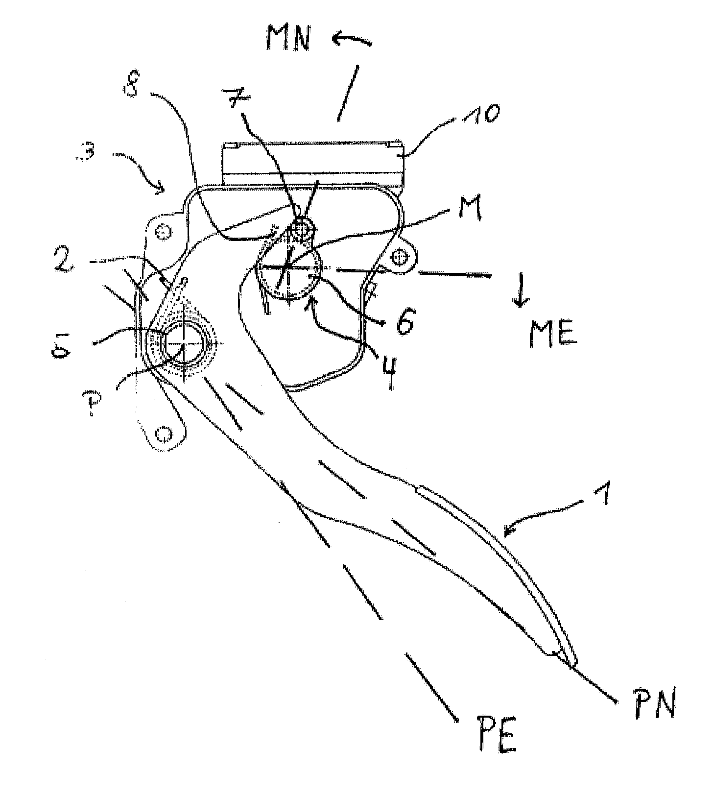
[0030]In order to increase the speed of a vehicle, the driver of the vehicle applies a force to a pedal lever 1. As the angle by which the pedal lever 1 is deflected from the zero position and with respect to the end position of the pedal lever becomes larger, the speed of the vehicle increases. In order to give the driver of the vehicle the sensation that he is controlling the speed, an opposing force counter to the force of the foot of the driver of the vehicle is increased at the pedal lever 1 as the pedal lever angle increases. This opposing force is generated, in particular, by a pedal return spring 2, a motor return spring 8 and a hysteresis element 5. As a rule, these devices are implemented by means of mechanical springs. These can be, in particular, tension springs and / or torsion springs. If the force which is applied to the pedal lever 1 by the driver of the vehicle and the opposing force which is generated by the return spring 2, the motor return spring 8 and the hysteres...


PUM


Abstract

A method for regulating motor vehicle speed by a pedal system having a force resetting device, including a pedal lever with a pedal return spring which can move the pedal lever to its zero position, an electric motor pivotable about a center of rotation which, when energized, can apply a resetting force to the pedal lever in the zero position direction, a motor return spring resets the electric motor in the zero position direction of the electric motor, and a control unit for controlling the electric motor. When the electric motor is de-energized, the pedal return spring, the motor return spring and a hysteresis element generate a passive pedal characteristic curve (PPCC). The PPCC can be changed by energizing the electric motor, and is variable additively at maximum with the available torque of the electric motor and substractively in the region of the spring constant of the motor return spring.

Description

CROSS REFERENCE TO RELATED APPLICATIONS[0001]This application is the U.S. National Phase Application of PCT International Application No. PCT / EP2010 / 056067, filed May 5, 2010, which claims priority to German Patent Application No. 10 2009 021 587.5, filed May 15, 2009, the contents of such applications being incorporated by reference herein.FIELD OF THE INVENTION[0002]The invention relates to a method for regulating the speed of a motor vehicle according to a method for regulating the speed in a motor vehicle by means of a pedal system having a force resetting device which is integrated in a housing, and to a device for carrying out the method.BACKGROUND OF THE INVENTION[0003]In the automobile industry there is an increasing trend to assist the driver of the vehicle in terms of driving safety, driving comfort and driving efficiency. Examples of this are cruise control systems and lane-keeping systems. In this context, the driving behavior is influenced in an assisting fashion on the...

Claims


Application Information

Patent Timeline
IPC IPC(8): G05G1/38
CPCB60K26/021B60W30/14Y10T74/20888G05G1/30G05G5/03B60W50/085
Inventor LEONE, CARMELODREWS, FRANKBAUMLER, JURGENBRANDT, THOMAS
Owner CONTI TEMIC MICROELECTRONIC GMBH
Learn More