
Display Array of Display Panel

a display panel and array technology, applied in the field of display arrays for display panels, can solve the problems of restricting the advantage of using this structure and increasing the complexity of the entire circuit, and achieve the effect of simple drive methods

Inactive Publication Date: 2012-04-05
AU OPTRONICS CORP
View PDF5 Cites 4 Cited by
  • Summary
  • Abstract
  • Description
  • Claims
  • Application Information

AI Technical Summary

Benefits of technology

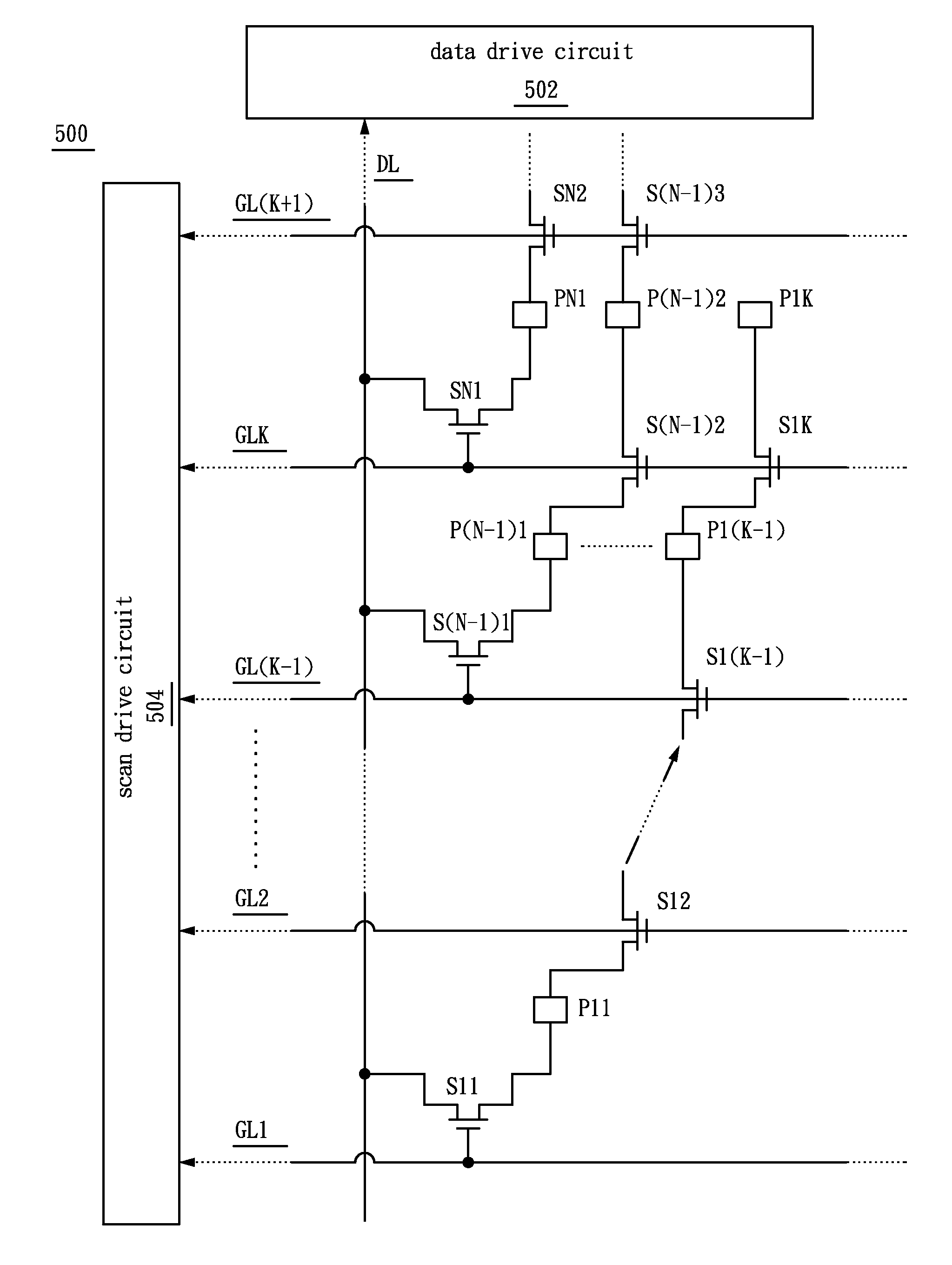
"The present invention provides a display array structure for a display panel that reduces complexity and simplifies the drive method. The structure includes a data line, scan lines, pixel electrodes, front-end switches, and intermediary switches. The front-end switch controls the first pixel electrode, while the intermediary switch controls the second pixel electrode. The operation of the switches is controlled by the scan lines. The display structure can be used to efficiently provide data signals to multiple pixel electrodes."

Problems solved by technology

These conditions will increase the complexity for the entire circuit and restrict the advantage of using this structure.

Method used


Image

  • Display Array of Display Panel
  • Display Array of Display Panel
  • Display Array of Display Panel

Examples


Embodiment Construction

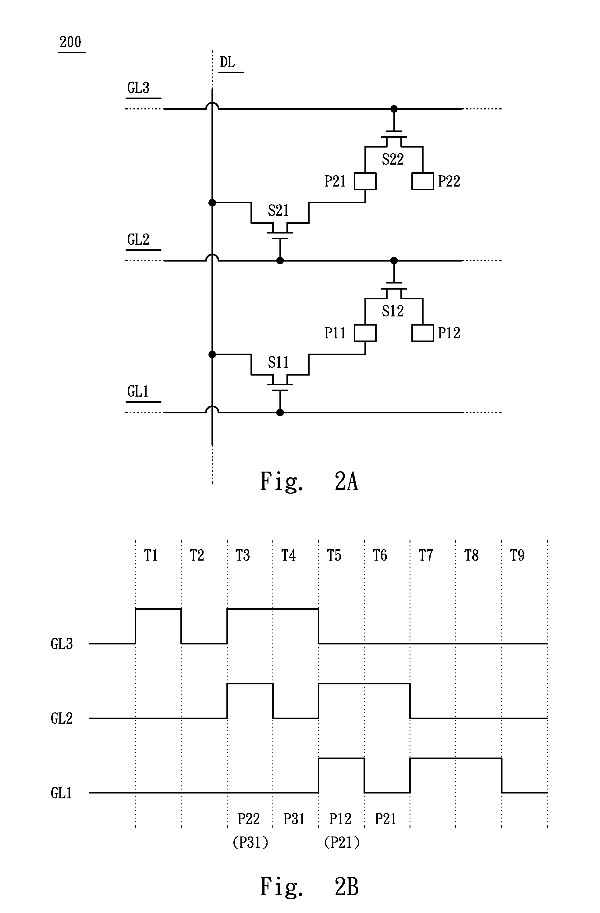
[0030]Referring to FIG. 2A, FIG. 2A illustrates the structure drawing of a display array 200 according to one preferred embodiment of this invention, wherein the structure comprises of a data line DL, a first scan line GL1, a second scan line GL2, a third scan line GL3, a first pixel electrode P11, a second pixel electrode P12, a third pixel electrode P21, a fourth pixel electrode P22, a first front-end switch S11, a second front-end switch S21, a first intermediary switch S12 and a second intermediary switch S22. The data signals required by the first pixel electrode P11, the second pixel electrode P12, the third pixel electrode P21 and the fourth pixel electrode P22 are transmitted respectively by the data line DL. The first front-end switch S11, the second front-end switch S21, the first intermediary switch S12 and the second intermediary switch S22 can be implemented with transistors. Te first pixel electrode P11 and the second pixel electrode P12 are located between the first s...


PUM


Abstract

A display array organization used in a display panel is provided. The display array includes a data line, a first scan line, a second scan line, a first pixel electrode, a second pixel electrode, a front-end switch and an intermediary switch. The first pixel electrode is connected to the data line with the front-end switch, and the second pixel electrode is connected to the first pixel electrode with the intermediary switch. The operation of the front-end switch and intermediary switch are controlled by the first and second scan line respectively. When only the front-end switch is activated, the first pixel electrode can receive the data signal from the data line. When both the front-end and intermediary switches are activated, the second pixel electrode can receive a data signal from the data line.

Description

RELATED APPLICATIONS[0001]The present application is a divisional of U.S. application Ser. No. 11 / 464,278, filed Aug. 14, 2006, which was based on, and claims priority from, Taiwan Patent Application Serial Number 95100632, filed Jan. 6, 2006, the disclosure of which is hereby incorporated by reference herein in its entirely.BACKGROUND[0002]1. Field of Invention[0003]The present invention relates to a display array for the display panel. More particularly, the present invention relates to a data line driving multiple pixel electrodes of a display array.[0004]2. Description of Related Art[0005]Optoelectronics technology has undergone rapid development over the past few years, digitalization trends for many kinds of electronic devices have expanded the technical levels and the application scopes for display panels. Consequently, display panels have evolved from conventional cathode ray tube (CRT) display screens into liquid crystal display (LCD) panels and the plasma display panels. T...

Claims


Application Information

Patent Timeline
Patent Type & Authority Applications(United States)
IPC IPC(8): G06F3/038
CPCG09G3/3659G09G3/3677G09G2320/0233G09G2310/08G09G3/3688
Inventor LIU, BIING-DERLIN, YU-CHIEHCHEN, SHAN-TE
Owner AU OPTRONICS CORP
Learn More