Image-shake correction device, lens barrel, and optical apparatus

a technology of image shake and correction device, which is applied in the field of image shake correction device, lens barrel, optical apparatus, etc., can solve the problems of increased size of lens barrel, sound or image collision, and increased size of components

Inactive Publication Date: 2012-04-05
CANON KK
View PDF2 Cites 23 Cited by
  • Summary
  • Abstract
  • Description
  • Claims
  • Application Information

AI Technical Summary

Benefits of technology

[0009]According to an aspect of the present disclosure, an image-shake correction device for correcting image shake includes a shift member configured to support a lens, a first driving unit configured to move the shift member in a first direction along a plane orthogonal to an optical axis, and a second driving unit configured to move the shift member in a second direction that is different from the first direction along the plane orthogonal to the optical axis, wherein each of the first and second driving units includes a magnet, a coil, and a yoke configured to generate a magnetic attractive force between the yoke and the magnet, with the shift member being moved by the magnetic attractive force developed as a result of energizing the coil, and wherein, to generate a magnetic attractive f

Problems solved by technology

However, the shift unit discussed in Japanese Patent Application Laid-Open No. 2002-196382 has an issue in that it involves a rotational movement within the optical-axis orthogonal plane of the shift member holding the correction lens.
If, as a result of this rotation, the shift member is brought into contact with the stationary member, there may be generated a collision sound or image disturbance.
Further, in the case where the components suffer damage from contact, there may be some problem involved in the driving of the shift member thereafter.
However, this results in an increase in the size of the components, which leads to an inc

Method used


Image

  • Image-shake correction device, lens barrel, and optical apparatus
  • Image-shake correction device, lens barrel, and optical apparatus
  • Image-shake correction device, lens barrel, and optical apparatus

Examples


Embodiment Construction

[0020]Various exemplary embodiments, features, and aspects will be described in detail below with reference to the drawings.

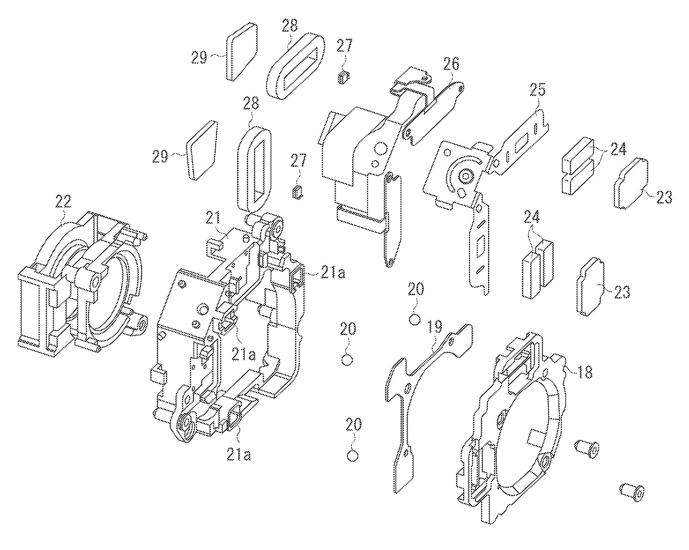
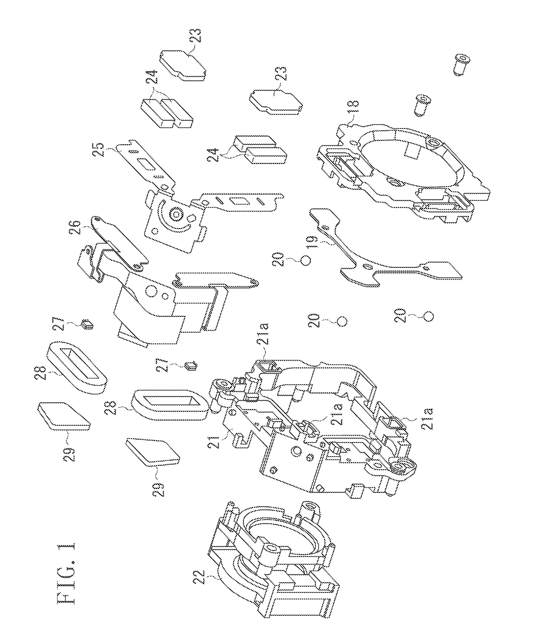
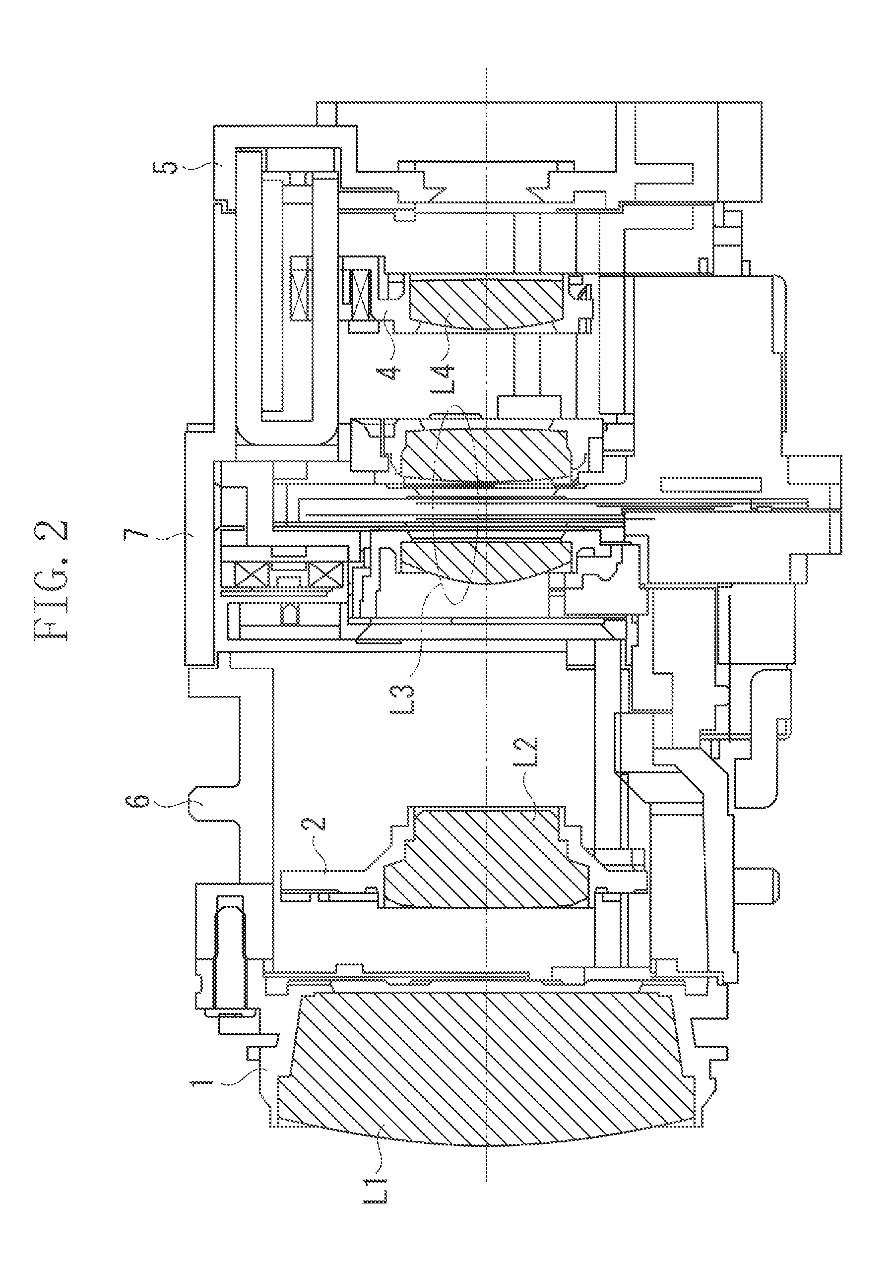
[0021]FIGS. 2 and 3 are diagrams illustrating a lens barrel equipped with a shift unit according to an exemplary embodiment. This lens barrel is provided so as to be detachable from a photographing apparatus (e.g., an optical apparatus) such as a video camera or a digital still camera, or so as to be integral therewith.

[0022]This lens barrel may be one having a variable magnification optical system (zoom lens) composed of four lens groups of positive, negative, positive, and positive refractive force, for example. Numeral L1 indicates a first, stationary lens group, and numeral L2 indicates a second lens group configured to move in an optical axis direction to perform a zooming function. Numeral L3 indicates a third lens group configured to move along an axis in a plane orthogonal to the optical axis to thereby effect image-shake correction, and numeral L4 indi...


PUM


Abstract

A yoke of an actuator for driving a shift moving frame in a pitch direction is shaped such that when the shift moving frame is moved in the pitch direction, a magnetic attractive force for reducing a moment acting on the shift moving frame due to a magnetic attractive force generated between the magnet and the yoke of an actuator for driving the shift moving frame in a yaw direction is generated between the yoke and the magnet of the actuator for driving in the pitch direction.

Description

BACKGROUND OF THE INVENTION[0001]1. Field of the Invention[0002]The present invention relates to an image-shake correction device configured to shift a lens to correct image shake occurring due to camera shake in an optical apparatus such as a digital camera or a video camera.[0003]2. Description of the Related Art[0004]In connection with the lens barrel of an optical apparatus such as a digital camera, there is a method of correcting image shake occurring due to camera shake or the like during shooting, according to which an image-shake correction lens is shifted along a plane orthogonal to the optical axis.[0005]Japanese Patent Application Laid-Open No. 2002-196382 discusses an image-shake correction device which is composed of a moving coil type shift unit (an image-shake correction device), wherein a magnet is arranged on a base member on a stationary side, and a yoke and a coil are arranged on a shift member holding a lens on a movable side. Three balls are arranged between the...

Claims


Application Information

Patent Timeline
IPC IPC(8): H04N5/228
CPCG03B5/00H04N5/23287G03B2205/0069G03B2205/0015H04N23/687
Inventor SATO
Owner CANON KK
Why Eureka
Try Eureka