Patient transfer device with differential belt-table speed control

a technology of speed control and transfer device, which is applied in the field of moving objects and devices, can solve the problems of uncomfortable pushing sensation on the body, jerky foster device, and patient discomfort of transfer devi

Active Publication Date: 2012-04-12
MEDIGLIDER
View PDF0 Cites 18 Cited by
  • Summary
  • Abstract
  • Description
  • Claims
  • Application Information

AI Technical Summary

Benefits of technology

[0011]It is therefore one object of the present invention to provide an improved patient transfer device.

Problems solved by technology

While the use of two counter-rotating belts to crawl under a patient greatly reduces frictional engagement which ideally eliminates skin shear for the patient, the prior art patient transfer devices can still create significant patient discomfort.
The Foster device can be particularly jerky since it is manually driven without any speed control.
The Patterson device further improves in this regard by using the slide assembly to keep the table assembly properly aligned and smoothly move under the patient, but even with the Patterson device some patients still have described an uncomfortable pushing sensation on the body.

Method used


Image

  • Patient transfer device with differential belt-table speed control
  • Patient transfer device with differential belt-table speed control
  • Patient transfer device with differential belt-table speed control

Examples


Embodiment Construction

)

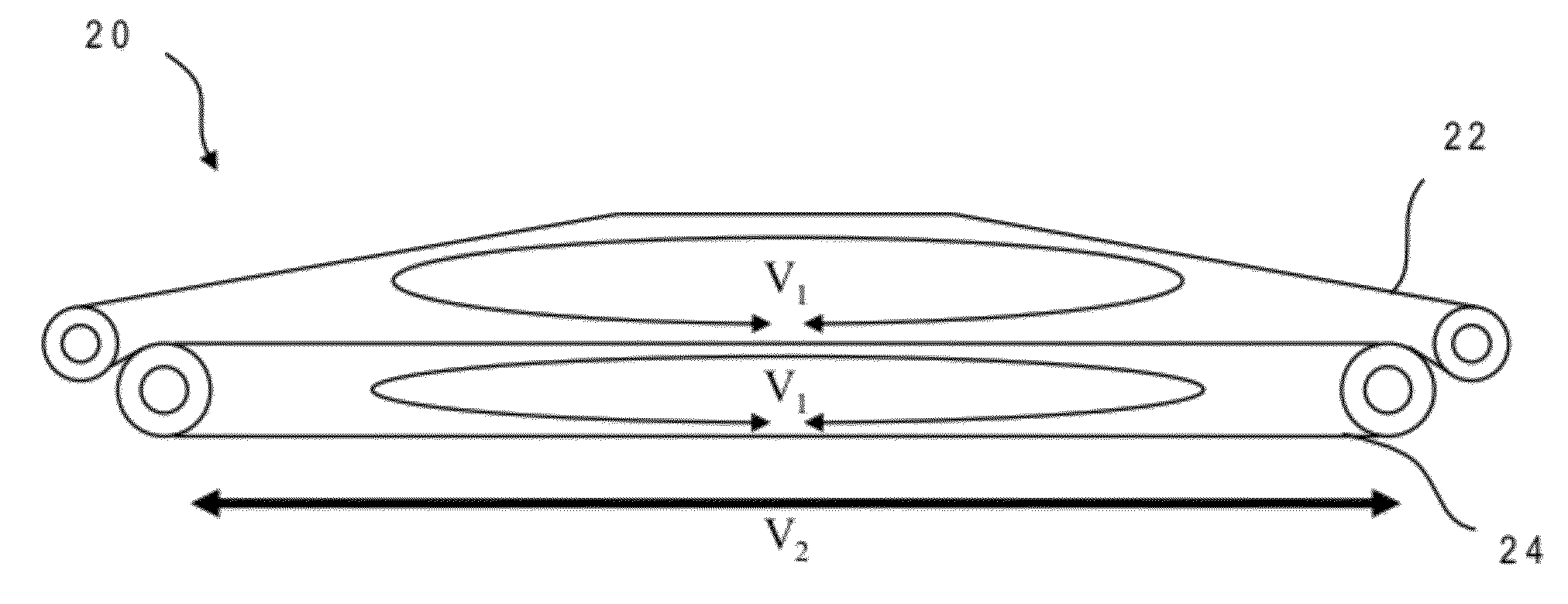
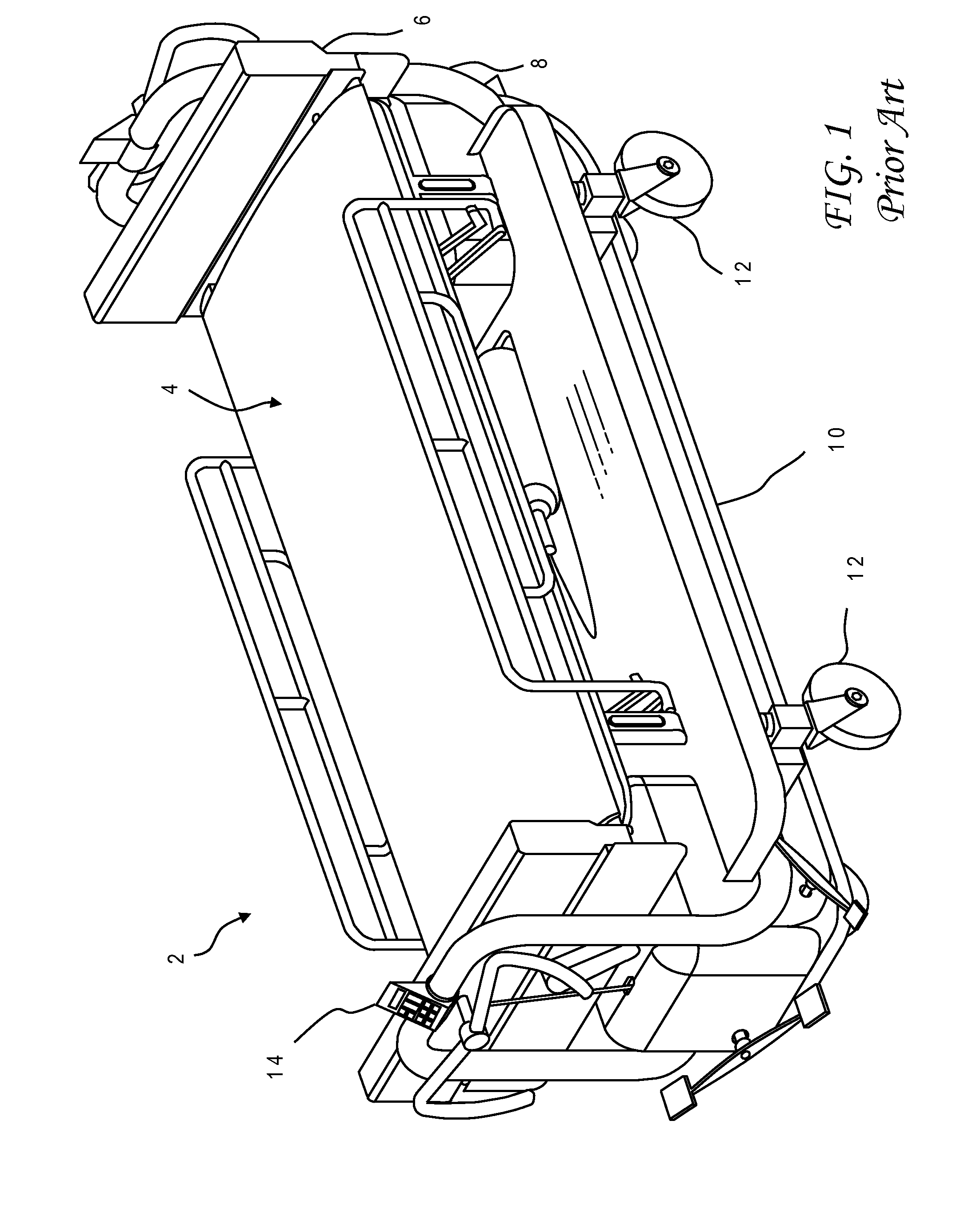
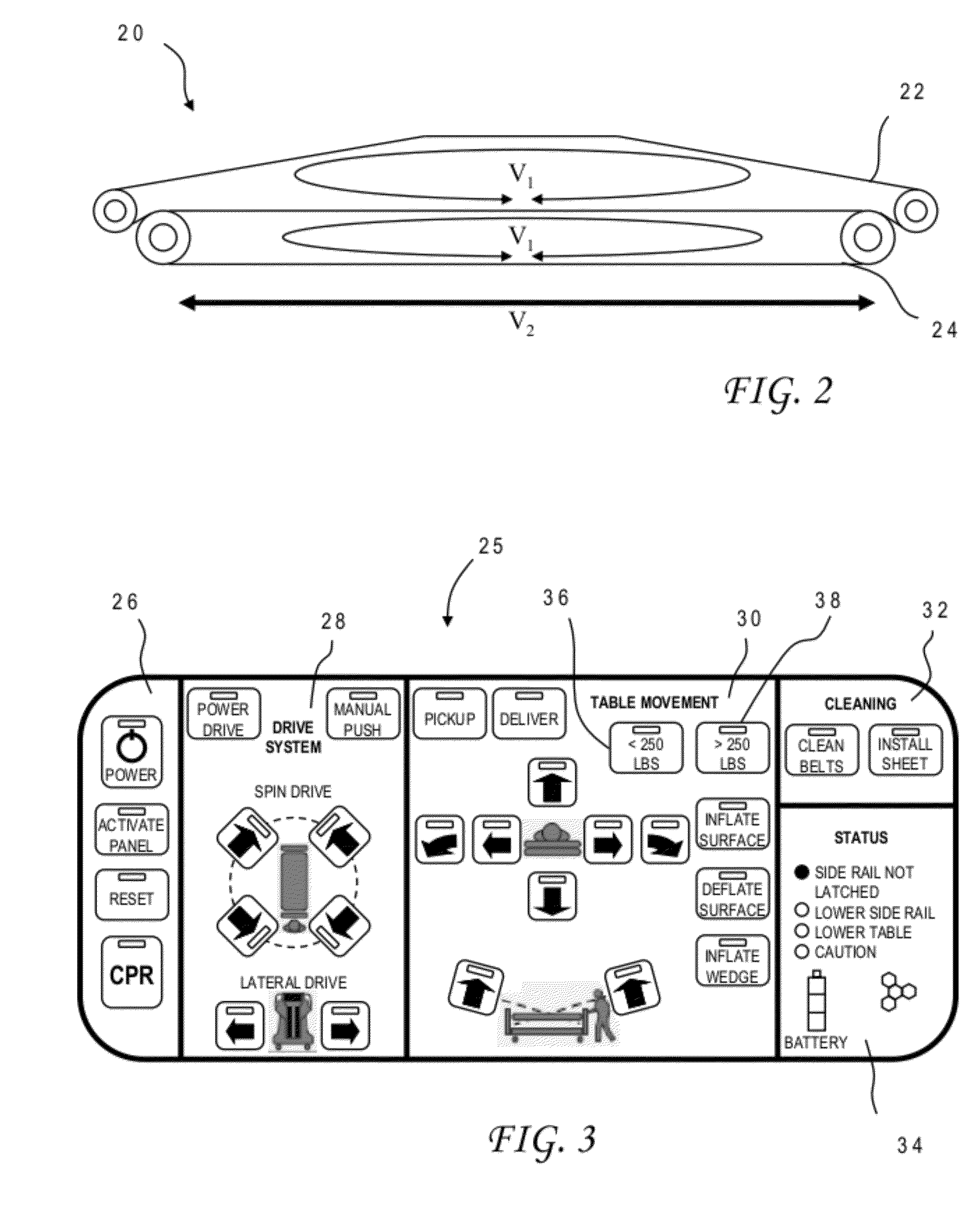
[0024]With reference now to the figures, and in particular with reference to FIG. 2, there is depicted one embodiment 20 of a table assembly constructed in accordance with the present invention, used to acquire and deliver an object such as a patient. Table assembly 20 is generally comprised of an upper belt 22, and a lower belt 24. Details of the belt construction and support may include those features described in U.S. Patent Application Publication No. 2008 / 0289101, which is hereby incorporated. Those features may further include a slide assembly similar to that illustrated in FIG. 1 which is mounted to a wheeled base and which allows lateral movement of the entire table assembly 20 with respect to the base, while the base remains in a fixed position on the floor, for either patient acquisition or delivery.

[0025]In a preferred embodiment, upper and lower belts 22, 24 can be in either an engaged position or a disengaged position. In the engaged position, portions of upper and low...


PUM


Abstract

A patient transfer device includes a table assembly having upper and lower tables with counter-rotating upper and lower belts. Means are provided to move the table assembly toward an extended position with the upper belt moving at a rotational speed which is greater than a translational speed of the table assembly. Faster movement of the upper belt may be in response to a determination that the patient has a characteristic whose value is within a predetermined range. The patient characteristic may be patient weight, e.g., with the predetermined range being less than 250 pounds. In the illustrative implementation a patient transfer device of the present invention includes a control system having a keyboard for receiving user input indicating that the upper belt should be moved faster, and control logic responsive to the user input which controls speeds of motors that independently drive the upper belt and the table assembly.

Description

BACKGROUND OF THE INVENTION[0001]1. Field of the Invention[0002]The present invention generally relates to devices for moving objects, and more specifically to a method and device for transferring mobility-impaired persons, such as moving a hospital patient from a bed to a table.[0003]2. Description of the Related Art[0004]A wide variety of products have been designed to move objects from one location to another and, in particular, transfer mobility-impaired individuals such as patients. In a hospital or other medical setting, patients must often be transported from their beds to an examination table or operating table, and back again. Basic devices for transferring patients include stretchers that are carried manually by two attendants, and gurneys that can more easily be handled by a single attendant. A typical gurney (British trolley) has an elongate patient-support surface, a frame or chassis structure for the patient-support surface, and wheels or casters that facilitate moveme...

Claims


Application Information

Patent Timeline
Patent Type & Authority Applications(United States)
IPC IPC(8): A61G7/14
CPCA61G7/0507A61G2200/16A61G7/1046A61G7/1032
Inventor PATTERSON, RICHARD A.SMUCKER, RALPH M.
Owner MEDIGLIDER
Why Eureka
Try Eureka