Trigger assembly for parts checking jigs and the like

a technology of parts and triggers, applied in the field of parts checking jigs, can solve the problems of increased manufacturing costs, inability to easily disassemble, and assembly cannot be readily reconfigured, and achieve the effect of convenient abutting contact and easy reconfiguration

Active Publication Date: 2012-04-12
UNITED FASTENER & SUPPLY
View PDF14 Cites 3 Cited by
  • Summary
  • Abstract
  • Description
  • Claims
  • Application Information

AI Technical Summary

Benefits of technology

[0005]One aspect of the present invention is a trigger assembly for parts checking jigs and the like, including a pivoting trigger arm having an outer end portion configured for abutting contact with a formed part disposed in an associated checking jig, an inner end portion configured for abutting contact with a gauge that indicates the position of the formed part relative to the checking jig, and a central portion with a laterally extending bearing aperture about which the trigger arm pivots. A universal base has a lower face configured for abutting support on an associated portion of the checking jig, opposite side faces, opposite end faces and an upper face disposed generally parallel with and opposite the lower face. First and second pivot pin apertures are disposed in the side faces of the base and arranged in a longitudinally spaced apart relationship adjacent the opposite end faces, and extend laterally through the side faces for selective alignment with the bearing aperture in the trigger arm. A generally U-shaped channel extends along the lower face of the base through the end faces, and is configured to receive and retain the trigger arm for pivotal motion in the U-shaped channel. First and second gauge bushing apertures are disposed in the upper face of the base and arranged in a longitudinally spaced apart relationship adjacent the opposite end faces, and extend through the upper face and into the U-shaped channel at locations generally overlying the trigger arm to facilitate the abutting contact between the gauge and the inner end portion of the trigger arm. A pivot pin is shaped for close reception in the bearing aperture of the trigger arm and both of the first and second pivot pin apertures in the base. The pivot pin is selectively received in one of the first and second pivot arm apertures and supports the trigger arm in the U-shaped channel of the base adjacent an associated one of the end faces of the base for pivoting motion between extended and retracted positions. A spring has an inner end portion supported in the base, and an outer end portion abuttingly contacting the trigger arm at a location thereon between the bearing aperture and the inner end to bias the trigger arm toward the extended position. A gauge bushing is shaped for close reception in both of the first and second gauge bushing apertures in the base. The gauge bushing is selectively received in one of the first and second bushing apertures for positioning the gauge adjacent an associated one of the end faces of the base, whereby the trigger arm assembly can be readily reconfigured for placement at various locations on the checking jig by selective mounting of the trigger arm using the pivot pin in either one of the first and second pivot pin apertures, and selective mounting of the gauge bushing in either one of the first and second gauge bushing apertures.

Problems solved by technology

The various parts of these prior art trigger assemblies were press fit together, and could not be easily disassembled, nor could the assembly be readily reconfigured.
Consequently, a plurality of differently shaped trigger assemblies, with different length trigger arms and differently positioned gauge bushings, were required for a single jig, which results in increased manufacturing costs, and substantial costs associated with inventorying a large number of different trigger assemblies.

Method used


Image

  • Trigger assembly for parts checking jigs and the like
  • Trigger assembly for parts checking jigs and the like
  • Trigger assembly for parts checking jigs and the like

Examples


Embodiment Construction

[0041]For purposes of description herein, the terms “upper”, “lower”, “right”, “left”, “rear”, “front”, “vertical”, “horizontal” and derivatives thereof shall relate to the invention as oriented in FIG. 1. However, it is to be understood that the invention may assume various alternative orientations and step sequences, except where expressly specified to the contrary. It is also to be understood that the specific devices and processes illustrated in the attached drawings, and described in the following specification, are simply exemplary embodiments of the inventive concepts defined in the appended claims. Hence, specific dimensions and other physical characteristics relating to the embodiments disclosed herein are not to be considered as limiting, unless the claims expressly state otherwise.

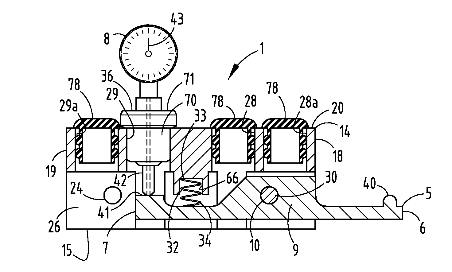
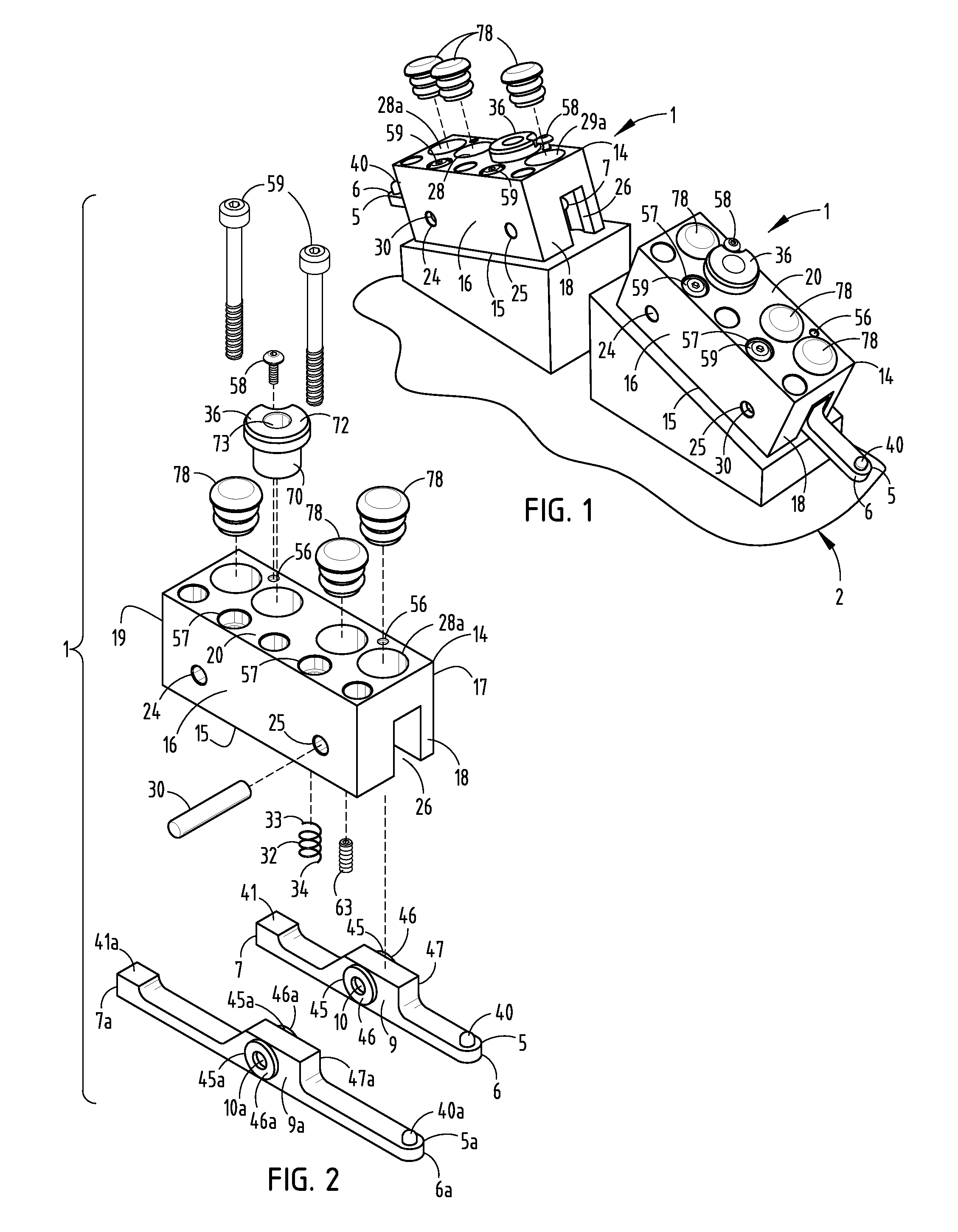
[0042]The reference numeral 1 (FIGS. 1 and 2) generally designates a trigger assembly embodying the present invention. Trigger assembly 1 is particularly adapted for use in conjunction with part...


PUM


Abstract

A trigger assembly for parts checking jigs and the like has a pivoting trigger arm with a central bearing aperture. A universal base is supported on the jig, and has two pairs of pivot pin apertures located adjacent opposite ends, a U-shaped central channel in the bottom face in which the trigger arm is received, and two laterally spaced gauge bushing apertures in the upper face. A pivot pin extends through the bearing aperture in the trigger arm and one pair of the pivot pin apertures in the base. A spring is mounted in the base and biases the trigger arm to an extended position. A gauge bushing is received in one of the two bushing apertures, such that the trigger arm assembly can be readily reconfigured for placement at various locations on the jig by selective mounting of the trigger arm and the gauge bushing in selected ones of the associated base apertures.

Description

CROSS REFERENCE TO RELATED APPLICATION[0001]This application claims priority to U.S. Provisional Patent Application No. 61 / 390,296 filed on Oct. 6, 2010 entitled TRIGGER ASSEMBLY FOR PARTS CHECKING JIGS AND METHOD.BACKGROUND OF THE INVENTION[0002]The present invention relates to parts checking jigs and the like, and in particular to a trigger assembly therefor.[0003]Jigs are typically used to dimensionally check sheet metal parts, assemblies, and the like to ensure that they conform with design specifications. A plurality of trigger assemblies are typically positioned at the critical dimension points around the jig. Each trigger assembly normally includes a pivoting trigger arm having an outer end that abuts an adjacent portion of an associated formed sheet metal part to be checked, and an inner end configured to abut an associated checking gauge or dial indicator, which displays the precise position of the pivot trigger arm, so as to determine the exact shape and position of the sh...

Claims


Application Information

Patent Timeline
Patent Type & Authority Applications(United States)
IPC IPC(8): G01B3/00
CPCG01B3/22
Inventor KETELAAR, DANIEL J.SCHUILING, DAVID L.NAGLE, THOMAS K.
Owner UNITED FASTENER & SUPPLY
Why Eureka
Try Eureka