Pneumatic tire

a pneumatic tire and tire body technology, applied in the field of pneumatic tires, can solve the problems of large rigidity difference between a stepping side and a kicking side, decreased edge effect of the sipe, large amount of etc., to achieve the effect of maintaining an edge effect and suppressing toe and heel wear

Active Publication Date: 2012-04-19
TOYO TIRE & RUBBER CO LTD
View PDF3 Cites 16 Cited by
  • Summary
  • Abstract
  • Description
  • Claims
  • Application Information

AI Technical Summary

Benefits of technology

[0008]The present invention has been made in view of the above circumstances, and has an object to provide a pneumatic tire that can suppress toe and heel wear in a sipe while maintaining an edge effect by the sipe.

Problems solved by technology

In such a case, the sipes are uniformly closed by, for example, a backward and forward force loaded at the time of braking, and this gives rise to the problem that the inherent edge effect of the sipe is decreased.
This structure gives rise to the problem that rigidity difference between a stepping side and a kicking side is large in the wide part, and a toe and heel wear amount is large.
Therefore, the structures are difficult to achieve both the edge effect and the toe and heel wear suppressing effect, similar to the above JP-A-09-272312.

Method used


Image

  • Pneumatic tire
  • Pneumatic tire
  • Pneumatic tire

Examples


first embodiment

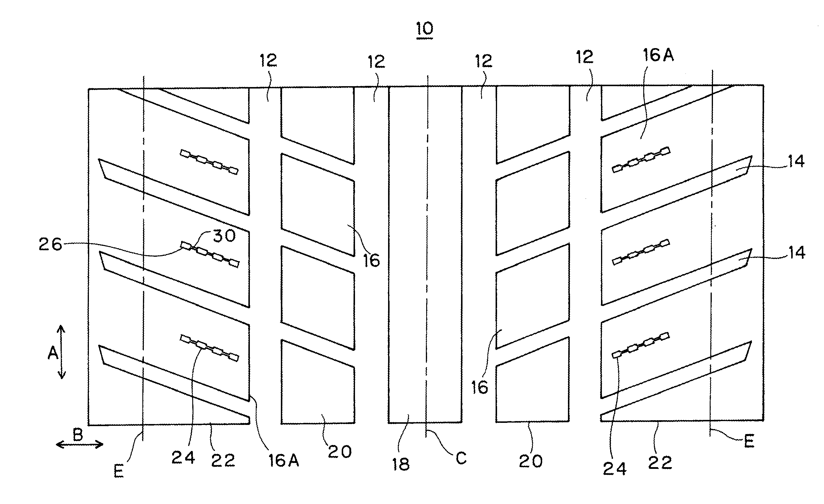
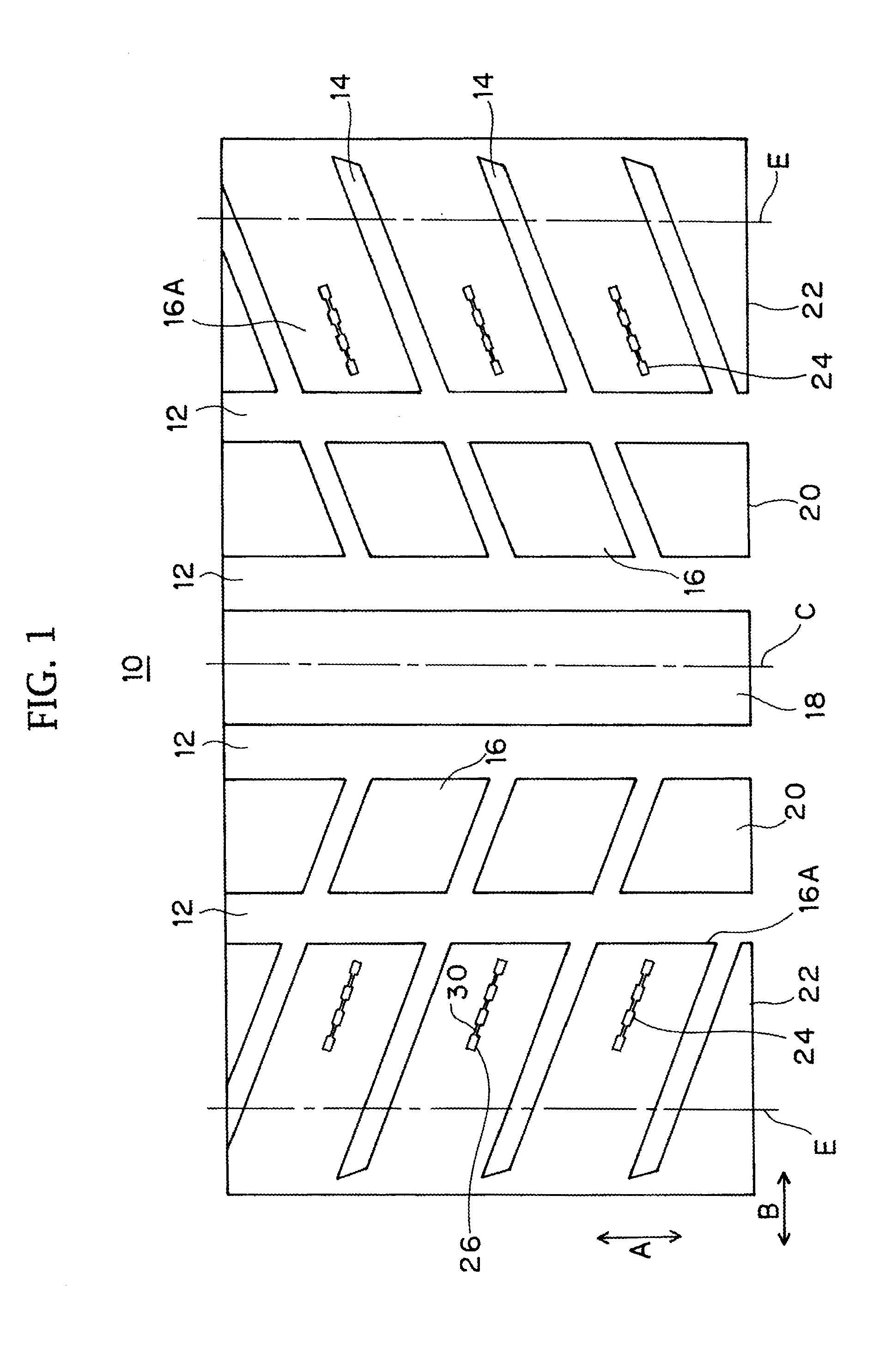
[0024]The pneumatic tire according to the first embodiment comprises a pair of right and left bead portions, a pair of right and left side wall portions, and a tread portion 10 provided between both side wall portions so as to mutually connect outward ends in a radial direction of the right and left side wall portions, although not shown. The tire further comprises a carcass extending across a pair of the bead portions. The carcass comprises at least one carcass ply which passes the side wall portion from the tread portion 10, the both ends of which being locked by a ring-shaped bead core, and reinforces the above each portion. The bead core is embedded in the bead portion. A belt comprising at least two layers of a rubber-covered steel cord layer is provided at an outer periphery side of the carcass in the tread portion 10, and the belt reinforces the tread portion 10 in the outer periphery of the carcass.

[0025]A plurality of circumferential grooves (main grooves) 12 extending in a...

second embodiment

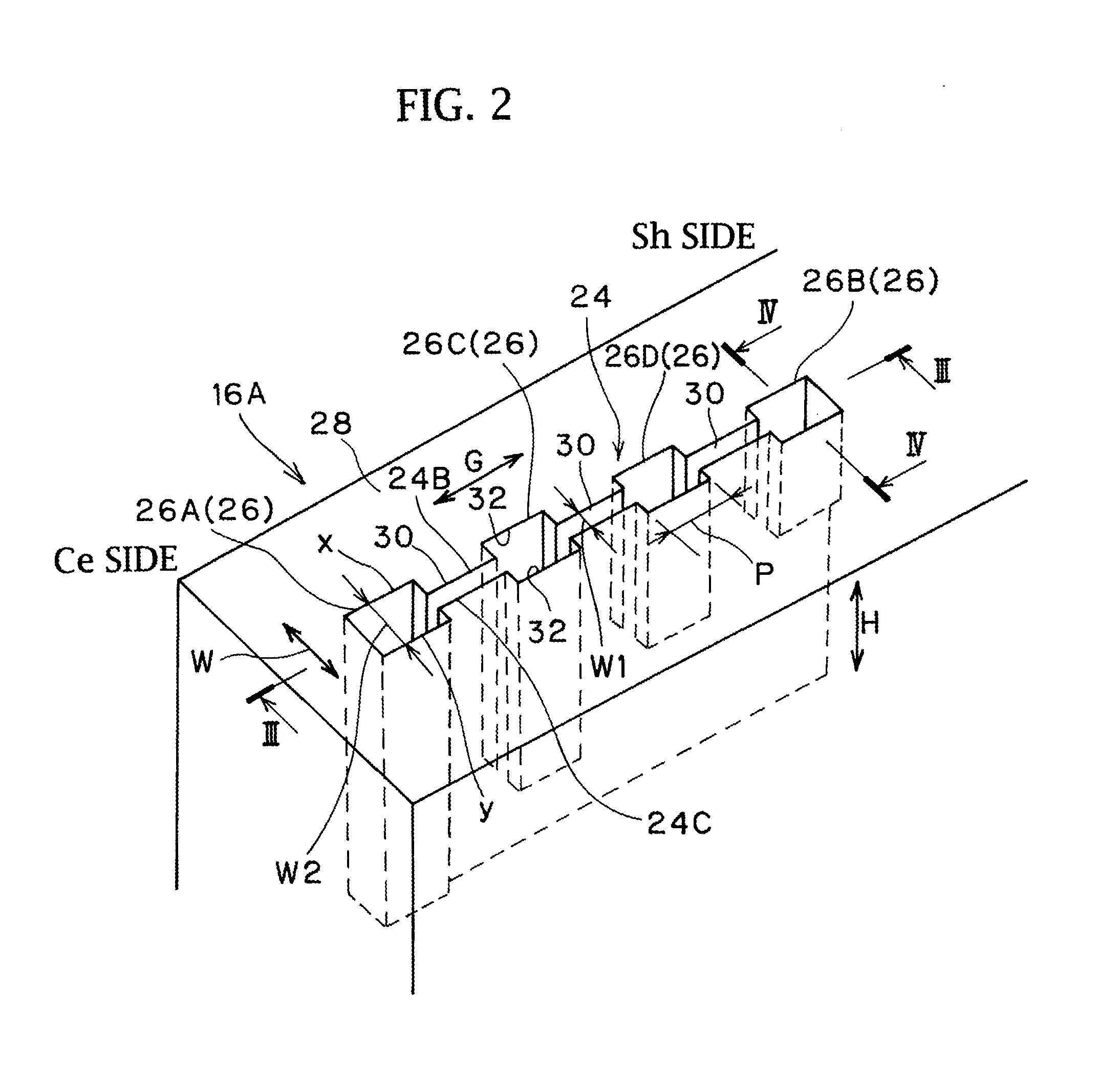
[0043]As shown in FIG. 6, the sipe 24 according to the second embodiment differs from that of the first embodiment in that the wide parts 26 are formed such that the size P in the sipe length direction G is gradually decreased with approaching the bottom side. FIG. 6 is a view that the sipe 24 as a hollow portion is shown in three dimensions (that is, a rubber constituting the block 16A is omitted), and corresponds to a blade shape of a mold for forming the sipe 24.

[0044]In detail, four wide parts 26 each are that a side 26F at its center line side Ce is vertically formed to the tread surface 28, and a side 26G at the ground contact end side Sh is formed in a inclined plane shape inclining to the center line side Ce as it approaches the sipe bottom side. However, each wide part 26 is that a planar bottom 34 is secured on the bottom of each wide part 26 so as to form a rectangular opening shape in a planar view over the entire sipe depth direction H.

[0045]In the second embodiment, th...

third embodiment

[0046]As shown in FIG. 7, the sipe 24 according to the third embodiment differs from that of the first embodiment in that the wide parts 26 are formed such that a groove width W2 is gradually decreased with approaching its bottom side.

[0047]In detail, four wide parts 26 are formed in an inclined plane shape inclining such that wall surfaces 26H, 26H facing the groove width direction W mutually approach as those approach the bottom side. However, each wide part 26 is that a planar bottom 34 is secured on the bottom of each wide part 26 so as to form a rectangular opening shape in a planar view over the entire sipe depth direction H.

[0048]In the third embodiment, the groove width W2 of the wide part 26 is formed so as to decrease as it approaches the bottom side, and this constitution can decrease the rigidity difference between the stepping side and the kicking side of each wide part 26. As a result, the toe and heel wear can further be suppressed. Other constitutions and the effects...


PUM


Abstract

In a pneumatic tire in which the sipe extending in a direction crossing a tire circumferential direction is provided on a land portion (block) of a tread portion, a wide part having a wide groove width is provided at three or more places in a length direction of the sipe, and the wide part and a narrow part are formed alternately on a tread surface along the sipe length direction. A plurality of the wide parts are extended in a sipe depth direction from the tread surface, and are provided by changing extended lengths in the sipe depth direction.

Description

CROSS-REFERENCE TO RELATED APPLICATIONS[0001]This application is based upon and claims the benefit of priority from the prior Japanese Patent Application No. 2010-230821, filed on Oct. 13, 2010; the entire contents of which are incorporated herein by reference.BACKGROUND OF THE INVENTION[0002]1. Technical Field[0003]The present invention relates to a pneumatic tire, and particularly relates to a pneumatic tire having a sipe formed on a land portion of a tread portion.[0004]2. Background Art[0005]A land portion such as a block or a rib is provided on a tread portion of a pneumatic tire, a cut having a narrow groove width called a sipe is sometimes provided on the land portion. Formation of the sipe increases running performance and braking performance on a snow and ice road surface and the like by its edge effect and water removal effect. Generally, the sipes are formed at a constant groove width in its length direction. In such a case, the sipes are uniformly closed by, for example,...

Claims


Application Information

Patent Timeline
Patent Type & Authority Applications(United States)
IPC IPC(8): B60C11/12B60C11/13
CPCB60C11/1218B60C11/0302Y10S152/03B60C11/1281B60C2011/1254B60C2011/1209
Inventor OHASHI, TOSHIYUKI
Owner TOYO TIRE & RUBBER CO LTD
Why Eureka
Try Eureka