
Fishing reel

Inactive Publication Date: 2012-04-26
FOSSADALUR EHF
View PDF14 Cites 0 Cited by
  • Summary
  • Abstract
  • Description
  • Claims
  • Application Information

AI Technical Summary

Benefits of technology

[0004]The present invention provides a novel shock absorbing system for fishing reels, where the rod or axle connecting the fly line spool to the brake system is made from two or more parts, where one of the rod or axle parts comprises shock absorbing, torsion properties. This means that when a fish takes the fly and swims away, the slack of the line is removed, the line stretches due to its properties and then fly line starts to run from the spool. Because of the torsion properties of the shock absorbing system, the tension of the fishing line is milder than in the traditional reel system, but this is due to the energy uptake through torsion moment in the system of the present invention. If the line force reaches the torsion moment resulting in overcoming the friction coefficient of the connecting brake plates, the brake plate system starts to transform the kinetic energy into heat. Under this process there is always energy stored in the system of the present invention, meaning that there is much lower lurch situation in the system. Furthermore, when the fish stops or turns, the energy stored will act like the fly line, leader and rod by releasing the energy by picking up line on the spool.

Problems solved by technology

The problem is that the dynamic friction coefficient is in all brake systems lower than the static friction coefficient, and the result is that the rod and line release some of its stored energy, resulting in a lurch quite often braking the leader and the fishermen loose the fish.

Method used


Image

  • Fishing reel
  • Fishing reel
  • Fishing reel

Examples


Embodiment Construction

[0017]The present invention will now be disclosed in relation to the following drawings.

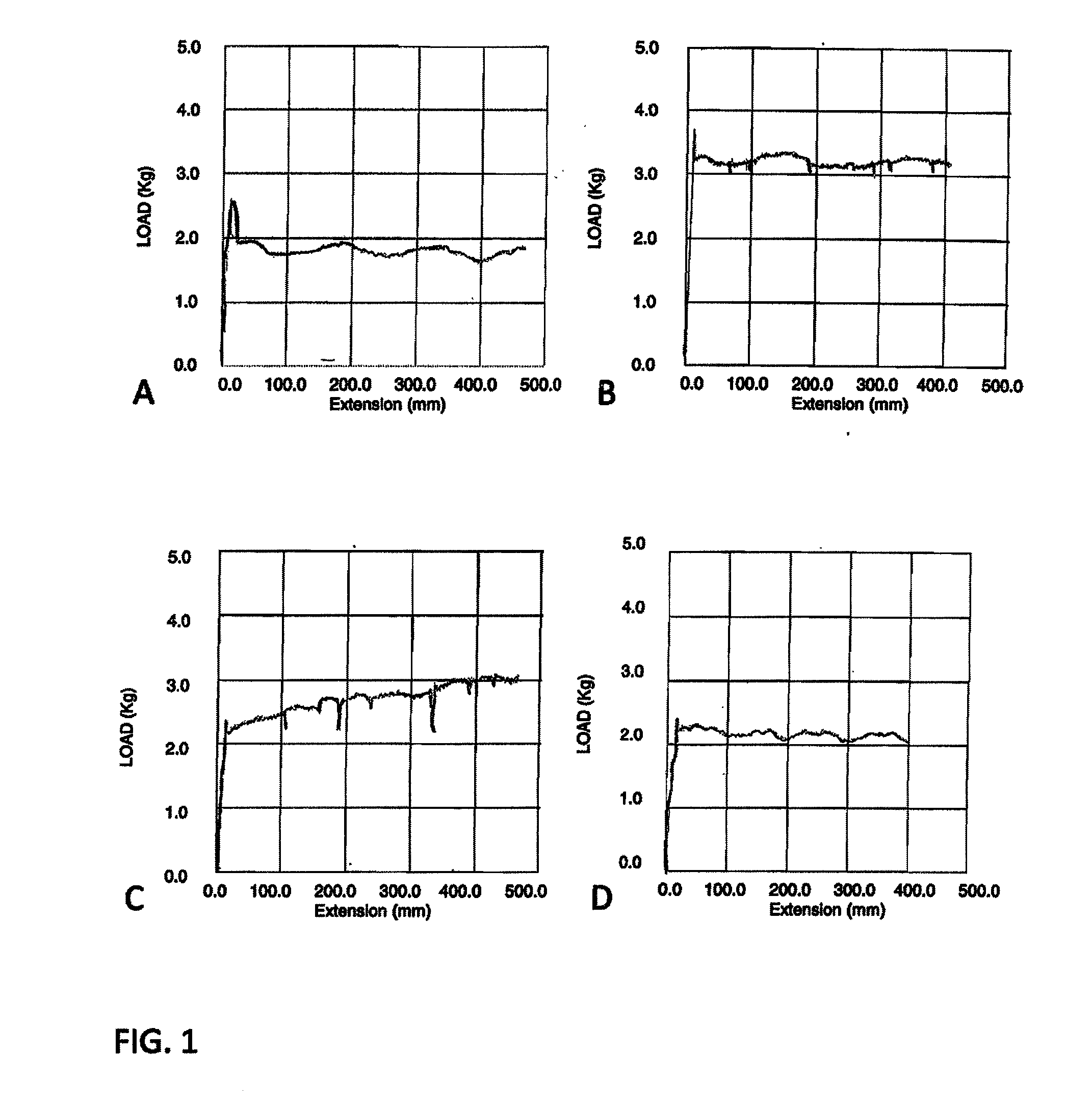
[0018]FIG. 1. shows diagrams of strain vs. turning of a spool on fishing reels for traditional (prior art) reels.

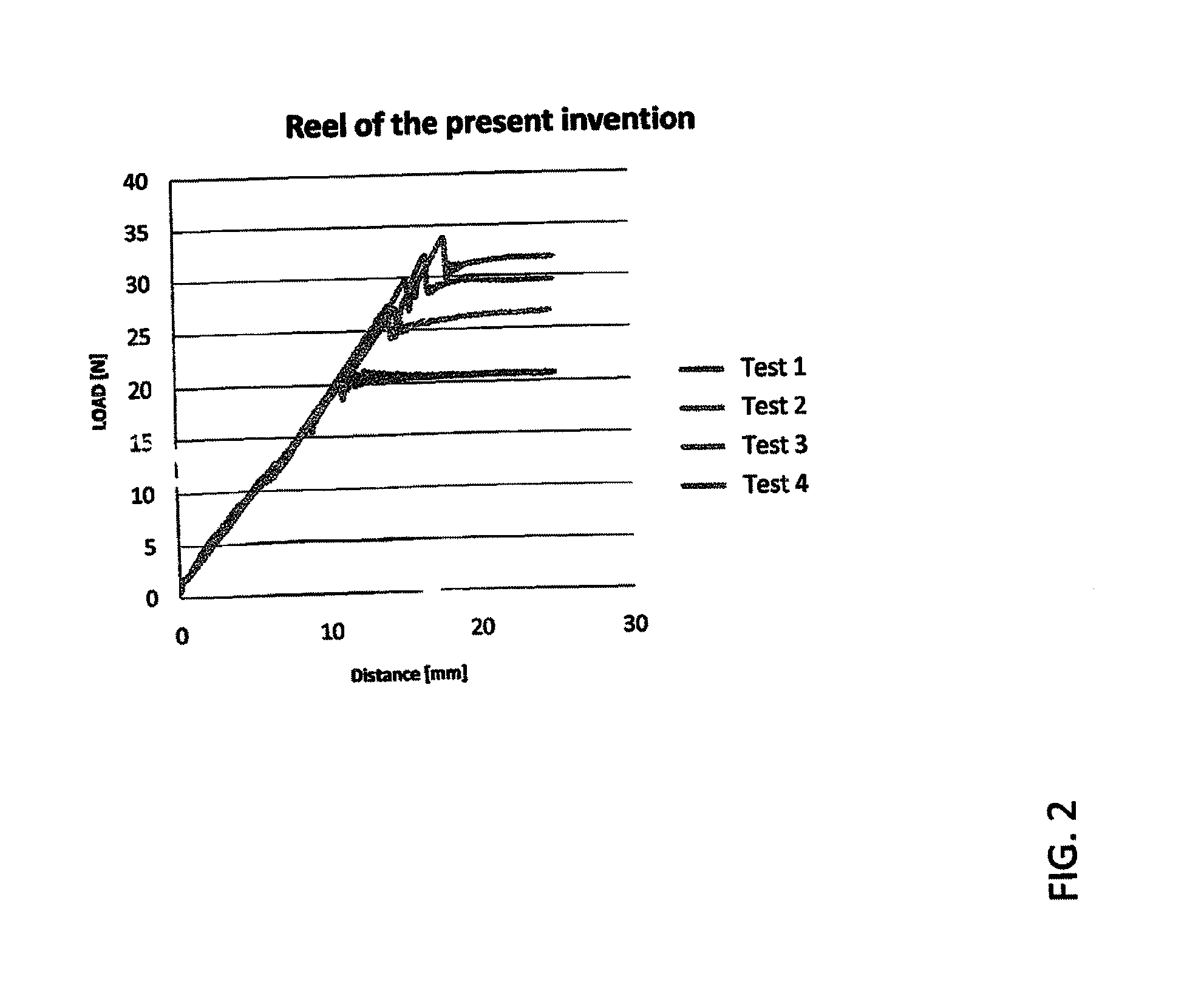
[0019]FIG. 2. shows a diagram of strain vs. turning of a spool on fishing reels for the fishing reel of the present invention.

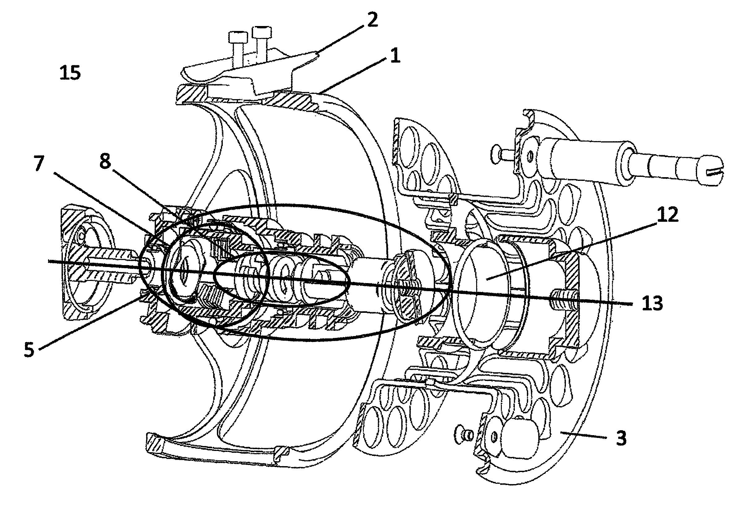
[0020]FIG. 3. shows an exploded view of the fishing reel of the present invention indicating major units and systems of the reel.

[0021]FIG. 4. shows an exploded view of the fishing reel of the present invention indicating the different components of the reel in further detail.

[0022]FIG. 5. shows the axle of the present invention.

[0023]FIG. 1 shows the difference between a fly fishing reel having a conventional brake system and a fly fishing reel of the present invention. Several prior art fly-fishing reels from some of the major produces were compared to the fishing reel of the present invention. The reels were tested in a tensile strength measuring device to sh...


PUM


Abstract

Fly fishing reels, a brake system, and a device for providing decreased tension on the fishing line and the leader are provided. In the system, the axle connecting the fly line spool to the brake system provides a shock absorbing system.

Description

FIELD OF THE INVENTION[0001]The present invention relates to fishing reels and more specifically the invention relates to a brake system and a device for providing a decreased tension on the fishing line and the leader.BACKGROUND OF THE INVENTION[0002]Fly-fishing reels are high-tech equipments used for sport fishing of many types of fish, both in salt water and in freshwater. The development of fly-fishing reels has been rapid in recent years, where use of new material for the reels has made them stronger, lighter texture and a beautiful addition to the redesign. The improvements that have been made in brake systems for the reels have transformed their effectiveness in fighting the fish.[0003]Traditional reels such as fly fishing reels have been for years treated as line carrier more than integrated part of the fishing equipment. This has lead to the fact that many fly fishermen use hands on the reel as brake when they fight the fish. Recent reels have been equipped with brake syste...

Claims


Application Information

Patent Timeline
IPC IPC(8): A01K89/033A01K89/016
CPCA01K89/017A01K89/016A01K89/05
Inventor THORBJORNSSON, INGOLFUREINARSSON, STEINGRIMUR
Owner FOSSADALUR EHF
Learn More