Light emitting diode package structure

a technology of light-emitting diodes and package structures, applied in the field of package structures, can solve the problems of reducing the inability of conventional phosphor powder coating methods to meet the current requirements, and the inability to achieve the consistency of spatial spectral distribution and illumination brightness, etc., to achieve the effect of improving the overall luminance performance of led package devices, improving the reliability of led package structures, and improving the uniformity of reflected ligh

Active Publication Date: 2012-04-26
EPISTAR CORP
View PDF16 Cites 7 Cited by
  • Summary
  • Abstract
  • Description
  • Claims
  • Application Information

AI Technical Summary

Benefits of technology

[0016]The present invention has the advantages as follows. Because of the configuration relationship that the LED and the package material having the fluorescent material are separated from each other without direct contact (remote phosphor), a certain distance exists between the LED and the fluorescent material for reflecting the light. Therefore, the overall luminance performance of the LED package structure and the uniformity of the reflected light are improved.
[0017]In the LED, the fluorescent material is remote from the heat source, that is to say, the fluorescent material does not directly contact the LED, so the reliability of the LED package structure is improved. Thus, the LED package structure is applicable in a package structure having multiple LEDs, and the manufacturing cost is greatly reduced at the same time.

Problems solved by technology

Thus, when the LED chip is in operation, the generated high heat energy will be directly transferred to the package material, and the properties of the phosphor powder change when being heated, resulting in decrease of the overall luminance performance of the LED package device.
Moreover, the current LED package techniques cannot achieve the consistency of the spatial spectral distribution and the illumination brightness of the illuminating light.
Package technique is one of the import facts that affect the performance of the LED, and in order to improve color uniformity of the LED and achieve high lumen output (light flux), the conventional phosphor powder coating method cannot meet the current requirements of the LED.
However, the electrophoretic coating technique disclosed in Patent '488 has the disadvantage of expensive manufacturing cost, so the cost of the LED cannot be reduced, and thus the LED manufactured through this method does not have a price advantage on the market.
Furthermore, in the method of attaching the phosphor coated sheet on the chip, the preparation process is complicated as the phosphor coated sheet has to be manufactured additionally; moreover, the step of attaching the phosphor coated sheet must be very accurate, so the yield cannot be controlled, thus resulting in increase of the manufacturing cost.

Method used


Image

  • Light emitting diode package structure
  • Light emitting diode package structure
  • Light emitting diode package structure

Examples


first embodiment

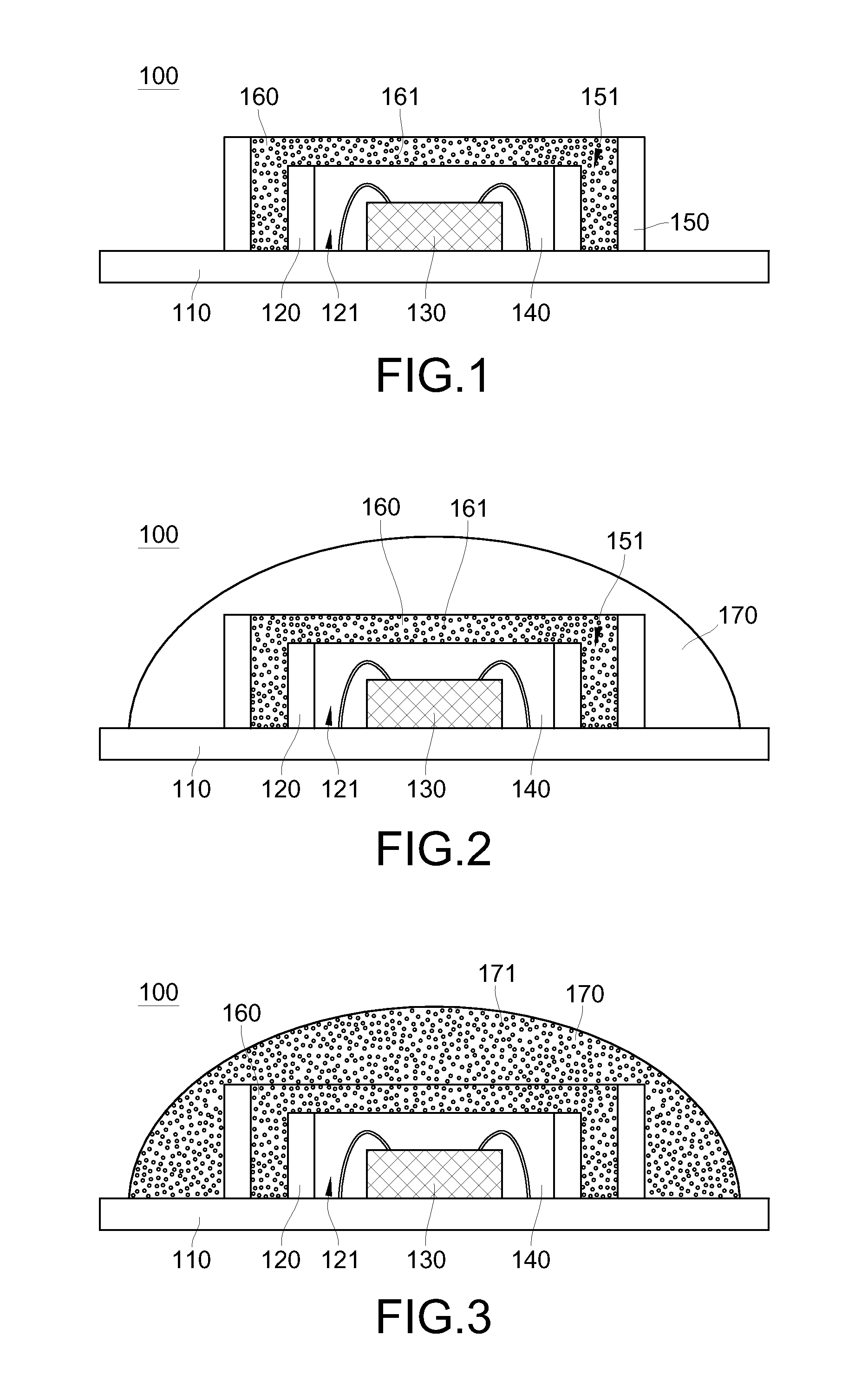
[0039]FIGS. 2 and 3 are side cross-sectional views of different aspects according to the present invention, and the implementation aspects disclosed in FIGS. 2 and 3 substantially have the same structure as the embodiment in FIG. 1, and only the differences between FIGS. 1, 2 and 3 would be described below.

[0040]As shown in FIG. 2, in addition to the substrate 110, the first enclosure 120, the LED 130, the first package material 140, the second enclosure 150, and the second package material 160, the LED package structure 100 of the present embodiment further includes a lens 170. The lens 170 covers the second enclosure 150 and the second package material 160, and the material of the lens 170 is a transparent material, for example, but not limited to, a polymer material or a glass material. The illuminating light emitted by the LED 130 is reflected to a wall surface of the lens 170, so the lens 170 can provide a better use of reflecting light.

[0041]Furthermore, as shown in FIG. 3, th...

second embodiment

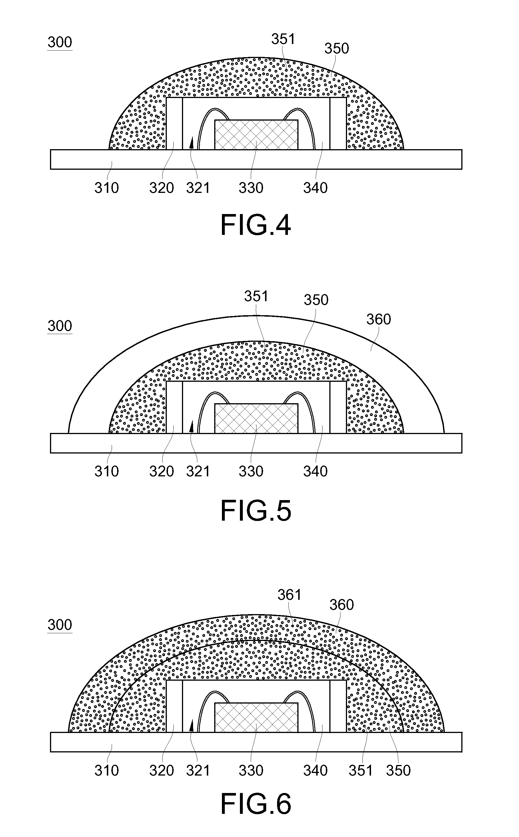
[0050]FIGS. 5 and 6 are side cross-sectional views of different aspects according to the present invention, and the implementation aspects disclosed in FIGS. 5 and 6 have substantially the same structure as the embodiment in FIG. 4, and only the differences between FIGS. 5 and 6 would be described illustrated below.

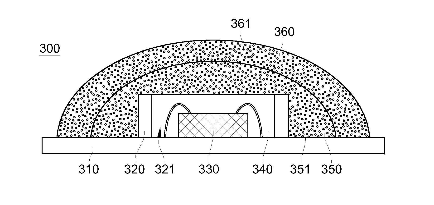
[0051]As shown in FIG. 5, in addition to the substrate 310, the enclosure 320, the LED 330, the first package material 340, and the second package material 350, the LED package structure 300 further includes a lens 360. The lens 360 covers the second package material 350, and the material of the lens 360 is transparent material, for example, but not limited to, a polymer material and a glass material. The illuminating light emitted by the LED 330 is reflected on a wall surface of the lens 360, so the lens 360 provides a better use of reflected light.

[0052]Furthermore, as shown in FIG. 6, the lens 360 of the present embodiment may further have a second fluorescent material...


PUM


Abstract

A light emitting diode (LED) package structure includes a substrate, at least one enclosure made of a transparent material, an LED, a first package material, and a second package material. The enclosure is disposed on a surface of the substrate, and forms a configuration area for disposing the LED therein. The first package material made of a transparent material is disposed in the configuration area and covers the LED. The second package material containing a fluorescent material covers the enclosure, the LED, and the first package material.

Description

CROSS-REFERENCE TO RELATED APPLICATIONS[0001]This non-provisional application claims priority under 35 U.S.C. § 119(a) on Patent Application No(s). 099135824 filed in Taiwan, R.O.C. on Oct. 20, 2010, the entire contents of which are hereby incorporated by reference.BACKGROUND OF THE INVENTION[0002]1. Field of Invention[0003]The present invention relates to a package structure, and more particularly to a light emitting diode (LED) package structure of a package type in which light emitting elements do not directly contact a fluorescent material.[0004]2. Related Art[0005]Due to low power consumption, high efficiency, and long life, LEDs are widely used in various application fields, for example, as light sources for backlight modules of notebook computers, monitors, mobile phones, TV sets, and liquid crystal displays (LCDs). Moreover, as more and more researchers work on the research and development of the LEDs, the luminous intensity of the LEDs already reaches a lighting level for d...

Claims


Application Information

Patent Timeline
Patent Type & Authority Applications(United States)
IPC IPC(8): H01L33/48
CPCH01L33/507H01L33/483H01L33/58H01L33/504H01L33/505H01L33/52H01L2224/48091H01L2924/00014H01L33/50
Inventor CHENG, TZU CHI
Owner EPISTAR CORP
Why Eureka
Try Eureka