Dried biological fluid spot punch device and related methods

a biological fluid and punching device technology, applied in water supply installation, laboratory glassware, instruments, etc., can solve the problems of high cost, high cost, and high cost of processing dried blood spots and other types of biological fluid spots, and achieve the effect of reducing the number of punching devices

Inactive Publication Date: 2012-05-03
AGILENT TECH INC
View PDF5 Cites 14 Cited by
  • Summary
  • Abstract
  • Description
  • Claims
  • Application Information

AI Technical Summary

Benefits of technology

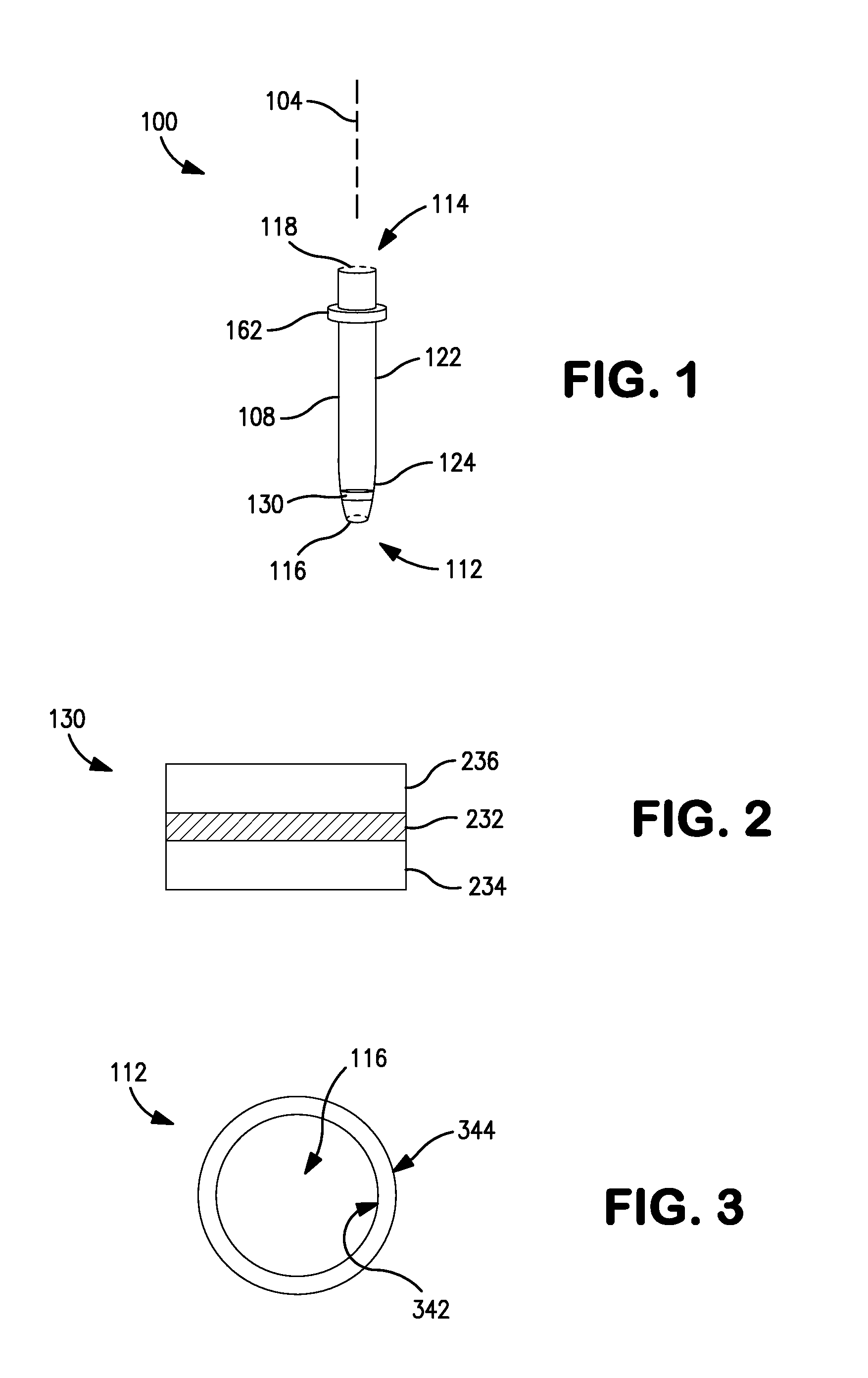
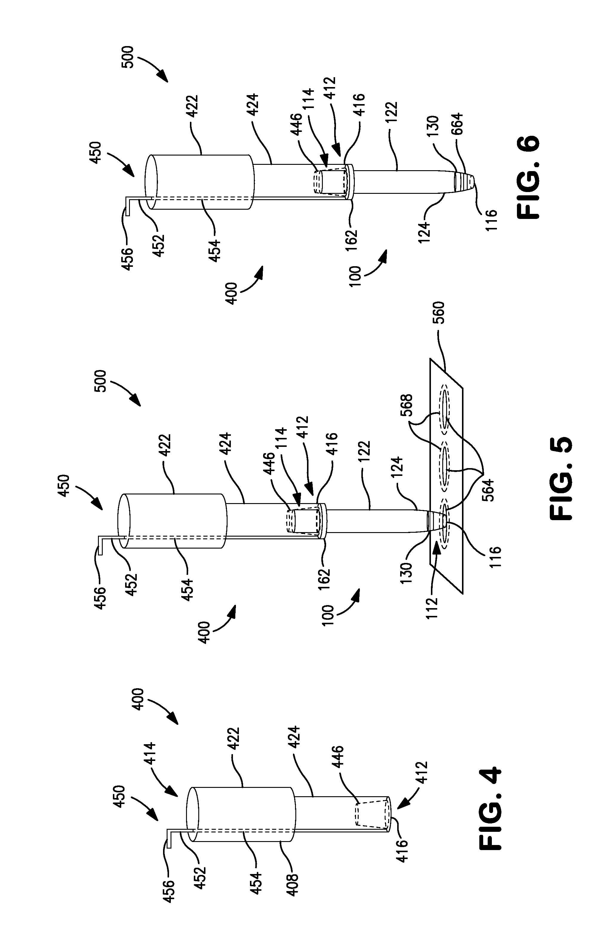
[0006]According to one implementation, a dried biological fluid spot punch device includes a tube, a fit, and a filter disposed on the fit. The tube includes a main section and a distal section adjoining the main section. The main section includes a proximal tube end circumscribing a proximal tube opening, and the distal section includes a distal tube end circumscribing a distal tube opening. The distal section further includes a distal tube wall having a tapered inside diameter that reduces from the main section to the distal tube opening. The frit is disposed in the distal section at a distance from the distal tube opening and is fixed in position by frictional contact with the distal tube wall. The punch device may also include a punching tool. The punching tool may include a body engaging the tube at the proximal tube end and an ejection mechanism configured for disengaging the body from the tube.
[0007]According to another implementation, a dried biological fluid spot punch device includes a tube, a fit, and a filter disposed on the fit. The tube includes a main section and a distal section adjoining the main section. The main section includes a proximal tube end circumscribing a proximal tube opening, and the distal section includes a distal tube end circumscribing a distal tube opening. The distal section further includes a distal tube wall having a tapered inside diameter that reduces from the main section to the distal tube opening. The fit is disposed in the distal section at a distance from the distal tube opening and is fixed in position by frictional contact with the distal tube wall. The tube may be composed of an organic polymer having a Rockwell hardness of 89 or greater.
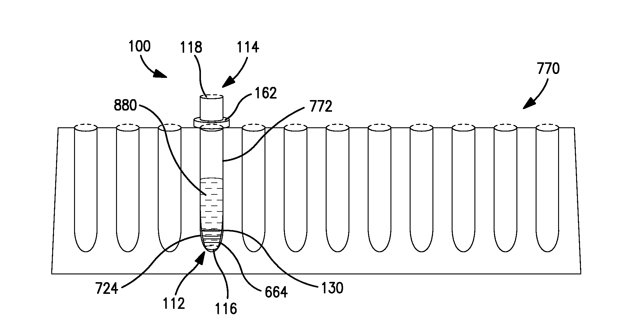
[0008]According to another implementation, a method is provided for acquiring a biological fluid sample from a substrate that includes one or more dried biological fluid spots. A dried biological fluid sample unit is formed. The sample unit includes a portion of the substrate and a selected dried biological fluid spot carried by the portion. The sample unit is formed by operating a tube to punch through the substrate at the portion, separating the sample unit from the substrate, passing the sample unit through a distal opening of the tube, and positioning the sample unit in the tube between the distal opening and a frit of the tube. The tube is inserted into a container until the tube forms a liquid seal with a surface of the container, and such that the distal opening, the sample unit, the frit, and a filter disposed on the frit are submerged in an elution solvent contained in the container. An analyte-inclusive liquid sample matrix is formed above the frit, by maintaining the tube in the container for a period of time sufficient for analytes to be eluted from the sample unit, pass through the filter and the frit, and be carried in the elution solvent at a desired concentration.
[0009]According to another implementation, a method is provided for acquiring a biological fluid sample from a substrate that includes one or more dried biological fluid spots. A dried biological fluid sample unit is formed. The sample unit includes a portion of the substrate and a selected dried biological fluid spot carried by the portion. The sample unit is formed by operating a tube to punch through the substrate at the portion, separating the sample unit from the substrate, passing the sample unit through a distal opening of the tube, and positioning the sample unit in the tube between the distal opening and a frit of the tube. The tube is inserted into a container until the tube forms a liquid seal with a surface of the container, and such that the distal opening, the sample unit, the frit, and a filter disposed on the frit are submerged in an elution solvent contained in the container. The filter is configured as a sorbent for analytes, such that analytes eluted from the sample unit are retained on the filter.
[0010]According to another implementation, a kit is provided for a dried biological fluid spot punch device. The kit includes a tube, a frit, and a filter. The tube includes a main section and a distal section adjoining the main section. The main section includes a proximal tube end circumscribing a proximal tube opening, and the distal section includes a distal tube end circumscribing a distal tube opening. The distal section further includes a distal tube wall having a tapered inside diameter that reduces from the main section to the distal tube opening. The frit is configured to be disposed in the distal section at a distance from the distal tube opening and fixed in position by frictional contact with the distal tube wall. The filter is configured to be disposed on the frit. The kit may also include a punching tool. The punching tool may include a body configured for engaging the tube at the proximal tube end and an ejection mechanism configured for disengaging the body from the tube.

Problems solved by technology

The processing of dried blood spots and other types of biological fluid spots has many problems.
Even with the use of cleaning and sterilization procedures, the repeated use of the same punching device can cause carryover and cross-contamination.
Moreover, steel is generally not considered to be readily disposable as compared to other types of materials such as various plastics.
Also, conventional processing of dried biological fluid spots has not been compatible with automated assaying systems.

Method used


Image

  • Dried biological fluid spot punch device and related methods
  • Dried biological fluid spot punch device and related methods
  • Dried biological fluid spot punch device and related methods

Examples


Embodiment Construction

[0021]In the context of the present disclosure, the term “fluid” refers generally to liquid-phase materials and gas-phase materials, unless a liquid-phase material or a gas-phase material is specifically indicated. The terms “liquid-phase” and “liquid,” and “gas-phase” and “gas,” are used interchangeably. A liquid-phase material or liquid may be any liquid, such as a solution, suspension, slurry, multi-phase mixture or the like, and may include gaseous components (e.g., bubbles) and / or solid components (e.g., particles). A gas-phase material or gas may be any gas or vapor, and may include liquid components (e.g., droplets) and / or solid components (e.g., particles). A “dried fluid sample” or a “dried fluid spot” refers generally to a material that was initially provided in the liquid phase and was thereafter dried, such as by air drying.

[0022]In the context of the present disclosure, the term “analyte” refers generally to any sample molecule of interest—that is, a molecule on which a...


PUM

PropertyMeasurementUnit
volumeaaaaaaaaaa
diameteraaaaaaaaaa
distanceaaaaaaaaaa

Abstract

A dried biological fluid spot punch device includes a tube, a frit, and a filter disposed on the frit. The tube includes a main section and a distal section adjoining the main section. The main section includes a proximal tube end circumscribing a proximal tube opening, and the distal section includes a distal tube end circumscribing a distal tube opening. The distal section further includes a distal tube having a tapered inside diameter that reduces from the main section to the distal tube opening. The frit is disposed in the distal section at a distance from the distal tube opening and fixed in position by frictional contact with the distal tube wall. The punch device may also include a punching tool. The punching tool may include a body engaging the tube at the proximal tube end and an ejection mechanism configured for disengaging the body from the tube.

Description

FIELD OF THE INVENTION[0001]The present invention relates generally to dried biological fluid spot analysis and the formation and processing of dried biological fluid spot samples in preparation for subsequent analysis.BACKGROUND OF THE INVENTION[0002]Dried biological fluid spot analysis such as dried blood spot (DBS) analysis is becoming increasingly popular for pharmaceutical companies in clinical trials. Collection sites for clinical trials may sample blood spots (or other types of biological fluid spots) in the field, allow the spots to dry, and then ship the spots at a lower cost than liquid samples due to the non-biohazard status of dried blood spots and the less rigorous requirements for temperature control. Blood spotting is also becoming useful in preclinical work as analytical chemists are required to store samples for Incurred Sample Reanalysis (ISR) studies, and dried blood spots have proven to be an effective way to stabilize the analytes and the matrix. Typically, DBS ...

Claims


Application Information

Patent Timeline
Patent Type & Authority Applications(United States)
IPC IPC(8): B26D7/06
CPCB01L3/0275B01L2300/0672G01N2001/288G01N1/286B01L2300/0681Y10T83/2122Y10T137/0318
Inventor GRENZ, ROBERT LEEHUDSON, WILLIAM C.
Owner AGILENT TECH INC
Why Eureka
Try Eureka